AMX AXCENT3 AND AXCENT3 PRO INTEGRATED AXCESS SYSTEM Instruction Manual
Integrated axcess controllers
Hide thumbs
Also See for AXCENT3 AND AXCENT3 PRO INTEGRATED AXCESS SYSTEM:
- Schematics document (1 page) ,
- Specifications (2 pages)

Related Manuals for AMX AXCENT3 AND AXCENT3 PRO INTEGRATED AXCESS SYSTEM


Summary of Contents for AMX AXCENT3 AND AXCENT3 PRO INTEGRATED AXCESS SYSTEM
- Page 1 instruction manual Axcent Axcent Integrated Axcess Controllers A x c e s s C e n t ra l C o n t r o l l e r s...
- Page 2 RMA number. AMX Corporation is not liable for any damages caused by its products or for the failure of its products to perform. This includes any lost profits, lost savings, incidental damages, or consequential damages. AMX Corporation is not liable for any claim made by a third party or by an AMX Dealer for a third party.
-
Page 3: Table Of Contents
Table of Contents Table of Contents Product Information ....................1 Specifications ........................1 Installation .........................3 Installing Axcess Control Cards (Axcent3 Pro Only) ............3 Installing the Axcent3 into an Equipment Rack ..............3 Installing the AC-RK3 Rack Kit..................3 Installing the CSB Cable Support Bracket................. 4 Wiring the Axcent3 ...................... - Page 4 Table of Contents Axcent and Axcent Pro Integrated Axcess Controllers...
-
Page 5: Product Information
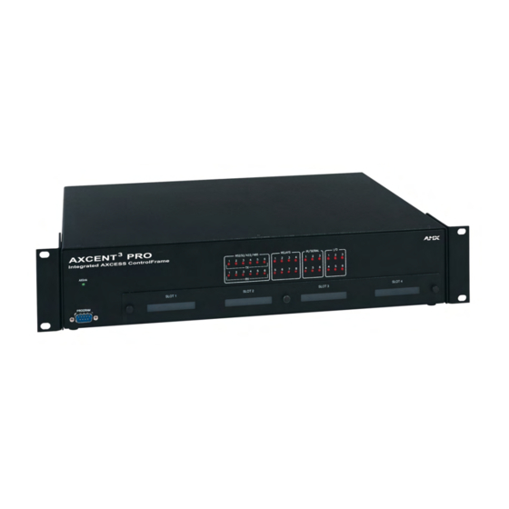
Product Information Product Information The Axcent and Axcent Pro Integrated Axcess Controllers are multi-port Central Controllers that can be programmed to control RS-232/422/485, relay, IR/serial/data, and input/output devices. The Axcent Pro combines the multi-port functionality with 4 card slots that can be populated with Axcess Central Controller cards to accommodate system growth. - Page 6 Product Information Specifications (Cont.) Rear Panel Components: RS-232/RS-422/RS-485 Six 9-pin (male) D-sub, RS-232/422/485 XON/XOFF, CTS/RTS, 300, 200 baud ports Status indicators 32 red LEDs that show RS-232/422/485, relay, IR/Serial/Data, and I/O port activity. The LEDs light when data activity occurs on the associated ports. AXlink indicator Green LED showing power and AXlink data activity.
-
Page 7: Installation
Installation Installation Installing Axcess Control Cards (Axcent Pro Only) To install Axcess Control Cards: 1. Discharge the static electricity from your body, by touching a grounded object. 2. Remove the thumbscrews and faceplate from the front panel (FIG. 1). Removable faceplate RS-232 / 422 / 485 RELAYS IR / SERIAL... -
Page 8: Installing The Csb Cable Support Bracket
Installation Mounting screw holes AC-RK3 Rack Kit mounting brackets Mounting Configurations Front Front FIG. 2 AC-RK3 Rack Kit mounting diagram 4. Connect the data cables into the controller. 5. Connect the power cable to the AXLINK/PWR connector to power-up the controller. Installing the CSB Cable Support Bracket Install the optional CSB Cable Support Bracket to secure the power and data cables connected to the controller. -
Page 9: Wiring The Axcent3
Installation CSB Cable Support Bracket Mounting screws 2", 4", 6" Mounting Configurations Mounting 2" screws 4" 6" FIG. 3 CSB mounting diagram 5. Align the bracket holes with the mounting brackets on the equipment rack. Then, start the mounting screws on both sides of the controller and tighten. 6. -
Page 10: Rs-232/Rs-422/Rs-485 Connections
Installation RS-232/RS-422/RS-485 connections FIG. 4 shows the RS-232/RS-422/RS-485 DB-9 (male) connector pinouts. The table below lists the connector pins, signal types, and signal functions. Pin 1 Pin 9 FIG. 4 RS-232/422/485 DB-9 (male) connector pinouts DB-9 Pinouts Wiring and Baud Configurations Signal Function RS-232... -
Page 11: Relay Connections
Installation GND wire on the AXlink/PWR connector when using a separate 12 VDC power supply. Do not connect the PWR wire to the AXlink connector’s PWR (+) opening. Relay connections Connect up to eight independent external relay devices to the 16-pin RELAYS connector. Use A for common and B for output. -
Page 12: Program Connector (Front And Rear Panels)
Installation Program connector (front and rear panels) Connect a programming cable to the PROGRAM connector on the controller. The table below shows the DB-9 connector pins and signals for the PROGRAM connector. Use the PROGRAM connector to download Axcess programs, and to set up control communication options using the OpenAxcess software program. -
Page 13: Axcess Programming
Axcess Programming Axcess Programming Device and Channel Numbers The following table lists the port type, device numbers, channels, with a brief description. Device and Channel Number Parameters Device Port Type Channels Description Numbers RS-232/422/485 1 - 6 1 - 255 6 Rs-232/422/485 control ports with XON/XOFF(transmit on/ transmit off), and CTS/RTS (clear to send/ready to send), 300, 200 baud. - Page 14 Axcess Programming Send_Commands for RS-232/422/485 Mode (Cont.) CTSPSH Syntax: Enables Pushes, ’CTSPSH’ Releases, and sta- Example: tus information to SEND_COMMAND RS232_1,’CTSPSH’ send to the Program via channel 255. Sets the RS232_1 port to detect changes on the CTS input. A contact closure is sometimes called a debouncing circuit. Sets the minimum Syntax: delay time before...
-
Page 15: Send_String Escape Sequences For Rs-232/422/485 Ports
Axcess Programming Send_String Escape Sequences for RS-232/422/485 Ports The table below lists the Send_String escape sequences for the RS-232/422/485 ports. Send_String Escape Sequences for RS-232/422/485 Ports "27,17,<1-255>" Sends a break character for the specified length of time. Variables: 1 - 255 = time in 100 microsecond increments "27,18,1"... - Page 16 Axcess Programming Send_Commands for the IR/Serial/Data Ports (Cont.) Channels 1-99 pulse as two digits. Channels 100 and greater, the one-hundredth digit pulses as 127. If IR function 21 (enter) exists, it follows the IR digit pulses. CTON sets Generates IR digit the pulse length for each digit and CTOF sets the time between each digit or any other pulses to select a pulse.
- Page 17 Axcess Programming Send_Commands for the IR/Serial/Data Ports (Cont.) CTON CTON sets the pulse length for each digit and CTOF sets the time between digits or any other pulse. Sets the IR pulse (single) on time for Syntax: each channel digit "’CTON’,<time>"...
- Page 18 Axcess Programming Send_Commands for the IR/Serial/Data Ports (Cont.) PTOF Syntax: Sets IR power-off "’PTOF’,<time>" pulse time after a Variables: power-on pulse in <time> = 0 - 255; Time is stored in permanent memory. System default is 15 (1.5 increments of .10 seconds).
- Page 19 Axcess Programming Send_Commands for the IR/Serial/Data Ports (Cont.) The CTON sets pulse length and CTOF sets time between pulses. Generates a single Syntax: <IR out> function "’SP’,<IR out>" pulse. Variables: <IR out> = 1 - 127 Example: SEND_COMMAND IR_1, "'SP',25" Pulses IR code 25, which decreases the volume level on the equipment connected to the controller.
-
Page 20: Send_Commands For Input/Output Ports
Axcess Programming Send_Commands for the IR/Serial/Data Ports (Cont.) XCHM Syntax: Sets the IR output ’XCHM [channel mode]’ format on the chan- Variables: nel specified with channel mode = Mode 0 - 3: the XCH command. Mode 0: [x][x]<x><enter> (default) Mode 1: <x><x><x><enter> Mode 2: <x><x><x>... -
Page 21: Standard Ir Function Order
Axcess Programming Standard IR Function Order The table below lists the standard function order for IR codes. Refer to the IRLIB instruction manual to download IR files. Standard IR Function Order Function Description Function Description Play > Channel up or + Stop [ ] Channel down or - Pause | | or still... -
Page 22: Program Port Commands
Axcess Programming Program Port Commands The PROGRAM port commands listed in the table below perform a wide variety of operations. You will need to connect an programming cable to the PROGRAM port on a master or slave controller, and your PC's serial port. The Controllers column shows the commands that can be used with Central controllers. - Page 23 Axcess Programming PROGRAM Port Commands (Cont.) Master Turns the device and channel numbers off. Syntax: OFF[Device, Channel] Variables: Device = 1 - 255 Channel = 1 - 255 Example: >OFF [52,1] Turns channel 1 on device 52 off. Master Turns the device and channel numbers on. Syntax: ON [Device, Channel] Variables:...
- Page 24 Axcess Programming PROGRAM Port Commands (Cont.) SET BASE DEVICE Master and Sets the AXlink base device number on the controller’s RS-232 port NUMBER Slave 1. Subsequent ports on the controller are incrementally set. If the device number is 1, the controller becomes an AXlink bus master, and if the device number is set to 2-xxx, the controller becomes a slave.
-
Page 25: Xmodem Timing Commands
Axcess Programming Xmodem Timing Commands The table below lists the Axcent and Axcent Pro Xmodem timing commands. Xmodem timeouts and retires exist to accommodate potential Ethernet delays and for consistency among and within products. Any of the Timeout commands will change timing for Axcess code download as well as SOFTROM transfer. -
Page 26: Setting Pc To Axcess Program Communications And Setting Device Number In Normal Mode
Axcess Programming 6. Press ENTER four times to lock-in the communication settings. Now, you can download an Axcess program to the controller. Choose one of the following modes to set: To reset the controller’s base device number, type SET BASE DEVICE NUMBER 1. To display everything you type in the Terminal window, type Echo On to activate echo mode. - Page 27 Axcess Programming Axcent and Axcent Pro Integrated Axcess Controllers...
- Page 28 Axcess Programming Axcent and Axcent Pro Integrated Axcess Controllers...
-
Page 29: Replacing The Lithium Batteries
Replacing the Lithium Batteries Replacing the Lithium Batteries There are two lithium batteries on the controller’s circuit card with a life of approximately five years. They protect stored commands against power loss. The batteries are not used when DC power is supplied to the controller. You should write down the replacement date on a sticker or label by adding five years to the date of installation, and then attach it to the rear panel for future reference. - Page 30 Replacing the Lithium Batteries 6. Carefully push the lithium battery, located in position B2, out of its socket, and remove with non-conduction pliers. With the rear of the unit facing you, insert the new battery with the positive (+) polarity side facing left. Do not use any type of conductive tools to remove the battery.
-
Page 31: Updating Firmware
To update: 1. Place the AMX SOFTROM diskette into drive A or B of your PC. 2. At the MS-DOS prompt C:>, type A:\ and press the ENTER key. 3. When the A:\> prompt appears on the screen, type SOFTROM and press the ENTER key. - Page 32 Updating Firmware Device Version number Type number number Firmware Loading status and device number FIG. 12 Loading message Firmware can be downloaded to multiple device numbers automatically. If multiple devices are selected, the bottom half of the loading bar will indicate the percentage complete for the selected devices.
- Page 33 Updating Firmware Axcent and Axcent Pro Integrated Axcess Controllers...
- Page 34 ATLANTA • BOSTON • CHICAGO • CLEVELAND • DALLAS • DENVER • INDIANAPOLIS • LOS ANGELES • MINNEAPOLIS • PHILADELPHIA • PHOENIX • PORTLAND • SPOKANE • TAMPA 3000 RESEARCH DRIVE, RICHARDSON, TX 75082 USA • 800.222.0913 • 469.624.8000 • 469-624-7153 fax • 800.932.6993 technical support • www.amx.com...
Need help?
Do you have a question about the AXCENT3 AND AXCENT3 PRO INTEGRATED AXCESS SYSTEM and is the answer not in the manual?
Questions and answers