
Subscribe to Our Youtube Channel
Related Manuals for AMX AXB-PT101530 POSITRACK CAMERA CONTROLLER


Summary of Contents for AMX AXB-PT101530 POSITRACK CAMERA CONTROLLER
-
Page 1: Instruction Manual
instruction manual AXB-PT10/15/30 PosiTrack Camera Controllers C a m e ra C o n t r o l l e r s... - Page 2 This warranty extends only to products purchased directly from AMX Corporation or an Authorized AMX Dealer. AMX Corporation is not liable for any damages caused by its products or for the failure of its products to perform. This includes any lost profits, lost savings, incidental damages, or consequential damages. AMX Corporation is not liable for any claim made by a third party or by an AMX Dealer for a third party.
-
Page 3: Table Of Contents
Table of Contents Table of Contents Introduction .......................1 Specifications ........................2 Lens Control Modes ......................3 Servomotor Mode........................3 Motor Mode ..........................4 Pan and Tilt Control......................4 Zoom, Focus, and Iris Control ................... 4 Sample Product Application ....................5 Pre-Installation ......................7 Configuration Settings ....................... - Page 4 Table of Contents Programming ......................27 Configuration Commands ....................27 Channel Commands ....................... 35 Pan/tilt functions........................35 Motor mode lens functions ..................... 36 Preset functions ........................36 Levels..........................38 Level applications........................38 Send_Commands ......................38 Diagnostic error values ......................41 Preset parameters and commands ..................
-
Page 5: Introduction
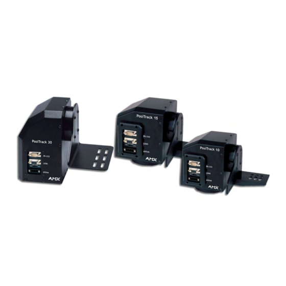
Introduction Introduction The AXB-PT10 PosiTrack 10, AXB-PT15 PosiTrack 15, and AXB-PT30 PosiTrack 30 Camera Controllers (FIG. 1) are camera/lens controllers used for precise camera-positioning applications. Each PosiTrack unit supports both AXlink and RS-232 control protocols and connects directly to an AXlink network. All controllers contain on-board intelligence for consistent motion and lens control. -
Page 6: Specifications
Introduction Specifications The following table lists the specifications for all PosiTrack units. Specifications Dimensions (HWD): AXB-PT10 Camera controller: 5.85" x 5.20" x 4.92" (14.86 cm x 13.22 cm x 14.70 cm) Camera mount: 0.65" x 2.26" x 3.23" (1.75 cm x 5.74 cm x 8.21 cm) Cradle support bracket: 3.64"... -
Page 7: Lens Control Modes
Introduction Specifications (Cont.) DIP Switches: • (S2) - RS-232 communication (baud rate) • (S5) - AXlink communication (device #) Presets: Stores up to 255 presets for pan, tilt, zoom, focus, and iris operations; 127 of those presets return a status when queried. Relays: Solid-state relays for servomotor lens mode control (zoom/focus speed/position and iris local/auto) -
Page 8: Motor Mode
Introduction Speed mode moves the lens when the voltage deviates from the center point of its range. The farther the voltage moves away from the center point of reference, the faster the lens motor moves. The lens must have POT outputs when recalling a preset in this mode,. The outputs pass to the PosiTrack unit, and when the received voltage level matches the level stored in the preset, the voltage returns to zero. -
Page 9: Sample Product Application
Power Supply PWR cable AMX AXB-EM232 (rear view) AXlink 12VDC RS-232 RS-232 / 422 AXlink AXlink AMX ABS (AXlink Bus Strip) AMX PS2.8 Power Supply PWR cable Application #2 - RS-232 AMX AXB-PT10 PC or other RS-232 controller AMX Local... - Page 10 Introduction AXB-PT10/15/30 PosiTrack Camera Controllers...
-
Page 11: Pre-Installation
Pre-Installation Pre-Installation There are four SPDT slide switches in the lens control section (FIG. 3). Three of the switches toggle the lens control selection between servomotor or motor mode hardware for control of zoom, focus, and iris. The fourth selects between ± 6 VDC and ± 12 VDC control for motor mode lens functions. -
Page 12: Setting Zoom, Focus, And Iris Switches To Servomotor Or Motor Mode
Pre-Installation AXlink S6 VOLT RS-232 S1 ZOOM S3 FOCUS S4 IRIS AXlink FIG. 3 Lens control section (back panel) Setting zoom, focus, and iris switches to servomotor or motor mode Both PosiTrack units support servomotor (+2.5 to +7.5 VDC operating range) and direct-drive motor (±... -
Page 13: Setting The Axlink Device Dip Switch (S5)
Pre-Installation The RS-232 factory default communications settings are: 9600 baud, No Parity, 8 bits, and 1 stop bit. The following table lists the RS-232 Port DB-9 (male) pinouts. RS-232 Port DB-9 (male) Pinouts Signal Function The following table lists the RS-232 DIP switch settings. RS-232 DIP Switch (S2) Settings Position Function... -
Page 14: Accessing The Axb-Pt10 And Axb-Pt15 Internal Jumpers
Pre-Installation The AXlink device number range is 1-255. The Device DIP switch positions determines their values, based on the following table: Device DIP Switch (S5) Settings and Values Position Value After setting the AXlink device number, remove and reconnect the AXlink connector on the PosiTrack unit to save the new number. -
Page 15: Accessing The Axb-Pt30 Internal Jumpers
Pre-Installation Pins that connect the control panel to the motherboard FIG. 7 Control panel removal for PT10 and PT15 6. Carefully pull the cover straight up from the main unit, until the bottom edge of the cover clears the connector panel and then slide it backwards (as seen in FIG. 8). FIG. -
Page 16: Setting The Internal Jumper Communication Mode
Pre-Installation BHSC screws (two screws on top) Connector panel (four screws) BHSC screws PosiTrack 30 (six screws on BHSC screws each side) (two on the rear) RS-232 LENS LENS POWER AXlink FIG. 9 Pan-head screw locations Setting the Internal Jumper Communication Mode 1. -
Page 17: Configuring An External Camera/Lens Power Supply
Pre-Installation For RS232 stand-alone mode, the 8-position AXlink Device DIP switch must be set to all off (down position). 4. Carefully place the cover back onto the main unit by sliding it over the internal gears and motherboard. 5. Align the Control panel screw holes. Make sure the cables are not pinched in the back panel or drive gears. - Page 18 Pre-Installation AXB-PT10/15/30 PosiTrack Camera Controllers...
-
Page 19: Installation
Installation Installation IMPORTANT! READ THIS DOCUMENT BEFORE MOUNTING CAMERA. Proper balance of the camera mount (with camera/lens/cradle) will result in optimal performance. Follow these balancing instructions prior to operation. Failure to balance the camera mount can result in poor performance. The PosiTrack units enable pan and tilt functionality for mounted camera/lens assemblies and provides lens control functions for teleconferencing lenses. -
Page 20: Pt10 And Pt15 Camera/Lens Mounting And Balancing
Installation Camera points this way when the pan drive is in Position marker the center of its range of motion (Home position) (on the outer surface) Ø 3.453" 87.7 mm 3.00 BHC" 76.20 mm 3.45" (87.7mm) FIG. 12 Tilt Hub (Mounting plate) dimensions Each PosiTrack unit can be mounted to camera mounts such as the TM-CAM, WM-CAM, and PM-CAM as shown in FIG. - Page 21 Installation 0.750" 0.750" 19.05 mm 19.05 mm 0.00" Position markers 0.750" 19.05 mm 0.250" Camera points 6.35 mm 0.00" in this direction 0.250" 6.35 mm 0.750" 0.56" 19.05 mm 39.62 mm FIG. 14 Tilt Hub dimensions for the PT10/15 units Do not lift the PosiTrack unit by the Camera/Lens cradle as this procedure could damage internal components.
- Page 22 Installation cradle balancing beam (bottom view) FIG. 16 Balancing the camera/lens cradle assembly 6. Re-attach the camera mount (with camera/lens) to the cradle support bracket using the two 1/2" screws. 7. Take the entire camera/mount and cradle assembly and align the lens with the Tilt Hub so that the vertical-axis intersects the center of the camera’s iris, as shown in FIG.
-
Page 23: Pt30 Camera/Lens Mounting And Balancing
Installation IMPORTANT! READ THIS DOCUMENT BEFORE MOUNTING CAMERA. Proper balance of the camera mount (with camera/lens/cradle) will result in optimal performance. Follow these balancing instructions prior to operation. Failure to balance the camera mount can result in poor performance. PT30 Camera/Lens Mounting and Balancing The camera/lens assembly should be mounted so the tilt axis is capable of going through the optical axis of the camera, assuming the optical centerline is between 1/2"... -
Page 24: Wiring The Connectors
Installation Camera/lens cradle assembly FIG. 19 Camera/lens cradle assembly mounting Tilt-axis mount slots FIG. 20 Balancing the camera/lens cradle assembly 7. Secure both the camera mounting and tilt-axis screws. 8. Take the entire camera/lens assembly and slide it along the Tilt Hub until the vertical-axis of the PT30 intersects the center of the camera’s iris. -
Page 25: Wiring Guidelines
Installation FIG. 21 shows the location of each connector on the AXB-PT10/15. AXB-PT10 (side view) Camera control RS-232 Control panel DB-9 (male) connector Lens control DB-15 high density (female) connector Lens Power switch Pin 1 power switch for DB-15 connector LENS POWER AXlink 4-pin (male) connector... -
Page 26: Preparing Captive Wires
Installation Preparing captive wires You will need a wire stripper and flat-blade screwdriver (approximately 1/8") to prepare and connect the captive wires. Never pre-tin wires for compression-type connections. 1. Strip 0.25 inch (6.35 mm) of insulation off all wires. 2. Insert each wire into the appropriate opening on the connector, according to the wiring diagrams and connector types described in this section. -
Page 27: Using The Axlink Connector With An External Rs-232 Control Device Or Pc (Stand-Alone Only)
Installation Using the AXlink connector with an external RS-232 control device or PC (Stand- Alone only) To use the AXlink 4-pin connector with a PC or other RS-232 controller, wire the AXlink connector to a DB-9 female connector, as shown in FIG. 23. Connector pins 2, 3, and 5 are used for data and ground. -
Page 28: Using The Lens Control Db-15 Hd (High Density) Connector
The following table lists the pinouts for motor mode lenses. Pin1 provides lens power from the PosiTrack’s own power supply when the lens power switch is set to AMX (left). Lens Control DB-15 HD Connector Pinouts for Motor Mode... -
Page 29: Pan Characteristics
Focus-POT wiper Pin 1 is not required if the lens is powered independently. This feature is controlled by the AMX/CAM switch on the connector panel. Pins 12-15 are required for Speed mode but are not required for Positional mode. Servomotor driven outputs are intended to drive servo-type motors only. The outputs have very low current (milliampere range) capability. -
Page 30: Tilt Characteristics
Installation Tilt Characteristics The tilt drive is factory set to a maximum tilt range of ± 90° (for a total of 180°). Tilt limit stops refer to the vertical range of motion available to the PosiTrack unit and are set via the Axcess program. -
Page 31: Programming
Programming Programming The AXB-PT10, AXB-PT15, and AXB-PT30 control capabilities for camera functions include: • Pan • Focus (servomotor; speed) • Tilt • Focus (motor drive) • Zoom (servomotor; positional) • Iris (servomotor; positional) • Zoom (servomotor; speed) • Iris (servomotor; speed) •... - Page 32 Programming Variables for the Configuration Commands (Cont.) Parameters Description Speed 0 to 127; where 0 is the slowest and 127 is the fastest (default). Deviation 0 to 127; where 0 is most accurate but can have some jitter. Default is 2, meaning the position can be within + 2 from the specified position.
- Page 33 Programming Configuration Commands (Cont.) CLEAR HOME Syntax: Clears the current SEND_COMMAND CAM,"’CLEAR HOME’" home position and This command also clears all presets. goes to the default setting and clears presets. CLEAR LIMIT ALL Syntax: Clears all of the limits. SEND_COMMAND CAM,"’CLEAR LIMIT ALL’" CLEAR LIMIT DOWN Syntax: Clears the tilt-down...
- Page 34 Programming Configuration Commands (Cont.) FOCUS This is applicable only if the FOCUS SIGNAL=S command is in effect, and the PRESET=SPEED FOCUS switch is set to the S position (servomotor mode). Sets the FOCUS Syntax: voltage output to recall SEND_COMMAND CAM,"’FOCUS PRESET=SPEED’" speed presets.
- Page 35 Programming Configuration Commands (Cont.) GET VERSION The Boot version sent back is determined by checking the version in flash (version 3.00 or memory. higher) Syntax: Displays the current SEND_COMMAND CAM,"’GET VERSION’" firmware version (Boot This command is issued from Terminal Emulator mode. When using a NetLinx and Download) on the master, the ’MSG ON’...
- Page 36 Programming Configuration Commands (Cont.) IRIS SIGNAL=S This setting corresponds to the S position (servomotor mode) setting on the IRIS switch. Sets the Iris output to be a servomotor output. Syntax: SEND_COMMAND CAM,"’IRIS SIGNAL=S’" The command for IRIS output to servomotor mode or motor mode MUST be configured to match the switch settings.
- Page 37 Programming Configuration Commands (Cont.) READ ALL Forces the device to read and update levels to the Central Controller. Syntax: SEND_COMMAND CAM,"’READ ALL’" RUN TESTS Runs and checks error values 244 and 245 to see if the gears are properly aligned to their respective grooves. Syntax: SEND_COMMAND CAM,"’RUN TESTS’"...
- Page 38 Programming Configuration Commands (Cont.) ZAP! Syntax: Initializes all memory in SEND_COMMAND CAM,"’ZAP!’" the unit. This includes speed settings, deviation settings, configuration settings, and all presets. Warning! This command clears all user-defined settings. ZOOM PRESET=POS Syntax: Sets the Zoom voltage SEND_COMMAND CAM,"’ZOOM PRESET=POS’" output to recall This is applicable only if the ZOOM SIGNAL=S command is in effect, and the positional presets...
-
Page 39: Channel Commands
Programming Channel Commands Use channel commands to program pan/tilt, servomotor positional, servomotor speed, and motor mode functions. Pan/tilt functions Pan/Tilt Functions Channel State Function Pan right at current speed Tilt down at current speed Pan left at current speed Tilt up at current speed Pan right at maximum speed (100%) Pan left at maximum speed (100%) Tilt down at maximum speed (100%) -
Page 40: Motor Mode Lens Functions
Programming Motor mode lens functions Motor Mode Lens Functions Channel State Function Iris (+) at current speed Zoom (+) at current speed (increases output voltage) Focus (+) at current speed Iris (-) at current speed Zoom (-) at current speed (decreases output voltage) Focus (-) at current speed Iris (+) at maximum speed Zoom (+) at maximum speed (output minimum voltage) - Page 41 Programming Status Channels Channel State Function Unit is panning Unit is tilting Unit has found its max pan left limit Unit has found its max pan right limit Unit has found its max tilt up limit Unit has found its max tilt down limit Unit has found its HOME position Unit is finding HOME position The following is an example of how to use the above functions to obtain a visual status of the...
-
Page 42: Levels
Programming Levels The following table lists the Axcess/NetLinx levels. Levels Level values Axcess/NetLinx level Range Direction 0 - 255 To PT Tilt 0 - 255 To PT Zoom 0 - 255 To PT Focus 0 - 255 To PT Pan Feedback 0 - 65535 From PT Tilt Feedback 0 - 65535 From PT... - Page 43 Programming Parameters - Send_Commands (Cont.) Parameters Description Time (optional) If specified, 0 to 255 in tenths of a seconds; if not specified, at current rate. Position 0 to 255; value of POT input. Corresponds to a position of the unit. 0 is one end of the POT and 255 is the other end. Not directly related to an output level voltage.
- Page 44 Programming Positional Commands (Cont.) This command can be used for all modes. Turns on the specified Syntax: output at the current "’G<output>L<position>’" speed until the Command forces output to go to a preset position using the POT input as a specified position (as reference.
-
Page 45: Diagnostic Error Values
Programming Positional Commands (Cont.) This command can be used for servomotor positional mode applications. Sets the ramp rate of Syntax: the specified output "’P<output>R<time>[U|D]’" voltage where time is Variables (See Parameters - Send_Commands section on page 38): the time to ramp the full range both down to up P - output = 3 - 5 and up to down or... -
Page 46: Preset Parameters And Commands
Programming Error Values and Descriptions Error Description Shows there is an error on the system. This value always appears in conjunction with another number. It acts as a precursor to any other error messages, as an announcement that an error has been found and the following values are the errors found. - Page 47 Programming The following table lists preset commands. Preset Commands CANCEL PRESET Examples: Immediately stops any SEND_COMMAND CAM, "’CANCEL PRESET’" active preset recall in motion. Syntax: Clears a preset from "’CP<preset>’" memory. Variables: preset = 1 - 255 Examples: SEND_COMMAND CAM, "’CP1’" Clears Preset 1.
-
Page 48: Rs-232 Commands
Programming Preset Commands (Cont.) SEND_COMMAND CAM,"’RP10S64’" Recalls preset 10. If any are in positional mode, the current voltages for zoom, focus, and/or iris will be ramped to the preset voltages at the current speed. If any are in speed mode, the motor drive outputs for zoom and/or focus will move at half speed (64). - Page 49 Programming RS-232 Commands (Cont.) CTSPSH Syntax: Enables pushes, "’CTSPSH’" releases, and status If CTS is high, channel 255 is On. information on channel Example: 255 for CTS hardware handshake input. SEND_COMMAND CAM,"’CTSPSH’" HSOFF Syntax: Disables hardware "’HSOFF’" handshaking (default). Example: SEND_COMMAND CAM,"’HSOFF’"...
-
Page 50: Rs-232 Send_Strings
Programming RS-232 Send_Strings PosiTracks have special Send_String escape sequences. If any of the three-character combinations listed below are found anywhere within a Send_String program instruction, they are treated as a command and not the literal characters. RS-232 Send_Strings "'27,18,0'" Clears the ninth data bit to 0 for all subsequent characters to be transmitted. It is used in conjunction with the 'B9MON' command. - Page 51 Programming General Format (Cont.) Byte No. Type Range Direction Pan Feedback 0-65535 From PT Tilt Feedback 0-65535 From PT Zoom Pot Feedback 0-65535 From PT Focus Pot Feedback 0-65535 From PT RS-232 Levels that are valid <LEVEL NO> are 0-7. The following table lists the request functions sent to PosiTrack units.
-
Page 52: Response Mask
Programming Response mask Data is automatically sent if the PosiTrack units receive a change request. The response mask should be disabled if the change request data is not used. Bits in the response mask (the Return/Respond Strings from the PosiTrack Units table) turn data off. (1=ON) DATA SENT (0=OFF) -
Page 53: Upgrading The Firmware
Upgrading the Firmware Upgrading the Firmware Upgrading the Firmware Using NetLinx Studio The NetLinx Studio application can perform firmware upgrades for both Axcess and NetLinx devices using the options in the NetLinx Studio Firmware sub-menu. Upgrading Firmware on Axcess Systems 1. -
Page 54: Upgrading The Firmware Using Softrom
RAM to flash memory, the unit will not operate at all when power returns. If you have not already installed the SOFTROM program, do so by following the steps contained on the AMX Control Disc. Configuration To configure the communication setting for the SOFTROM program: 1. - Page 55 Upgrading the Firmware 4. Using the up/down arrow keys, select the device to be programmed. 5. Press ENTER for each device as it is selected 6. Press F4 to program the selected device; a loading message appears. 7. Once the .TSK file has been downloaded, the device AXlink LED will begin to flash repeatedly for about 6 seconds while the on-board firmware is stored and updated.
- Page 56 DALLAS, TEXAS • LOS ANGELES, CALIFORNIA • MEXICO CITY, MEXICO • ONTARIO, CANADA • PHILADELPHIA, PENNSYLVANIA • SHANGHAI, CHINA • SINGAPORE • TAMPA, FLORIDA • WESTERLO, BELGIUM • YORK, ENGLAND 3000 RESEARCH DRIVE, RICHARDSON, TX 75082 USA • 800.222.0193 • 469.624.8000 • 469-624-7153 fax • 800.932.6993 technical support • www.amx.com...
Need help?
Do you have a question about the AXB-PT101530 POSITRACK CAMERA CONTROLLER and is the answer not in the manual?
Questions and answers