AMX AXB-PT15 POSITRACK CAMERA CONTROLLER Instruction Manual
Positrack camera controller
Hide thumbs
Also See for AXB-PT15 POSITRACK CAMERA CONTROLLER:
- Engineering drawing (1 page) ,
- Manual (2 pages) ,
- Instruction manual (56 pages)

Related Manuals for AMX AXB-PT15 POSITRACK CAMERA CONTROLLER


Summary of Contents for AMX AXB-PT15 POSITRACK CAMERA CONTROLLER
-
Page 1: Instruction Manual
instruction manual AXB-PT15 PosiTrack Camera Controller C a m e ra C o n t r o l l e r s... - Page 2 RMA number. AMX Corporation is not liable for any damages caused by its products or for the failure of its products to perform. This includes any lost profits, lost savings, incidental damages, or consequential damages. AMX Corporation is not liable for any claim made by a third party or by an AMX Dealer for a third party.
-
Page 3: Table Of Contents
Preparing the PosiTrack Controllers for communication............20 Using the lens control DB-15 HD (high density) connector............ 21 Pan Characteristics ......................22 Setting the adjustable pan-limit stops ..................23 Tilt Characteristics......................23 Setting the adjustable tilt-limit stops..................23 AXB-PT15 PosiTrack Camera Controller... - Page 4 Upgrading the Firmware ..................47 Communicating with the Controller via the Program Port ..........47 Verifying the current version of PosiTrack Firmware ............48 Upgrading the Firmware Using SOFTROM ..............50 Configuration.......................... 50 Downloading the Firmware ....................51 AXB-PT15 PosiTrack Camera Controller...
-
Page 5: Introduction
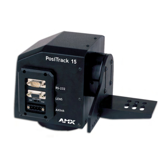
AXlink and RS-232 control protocols and connects directly to an AXlink network. All controllers contain on-board intelligence for consistent motion and lens control. Dual Camera/Lens Cradle Assembly FIG. 1 AXB-PT15 PosiTrack Camera Controller (side view) The following table shows the PosiTrack unit lens compatibility. PosiTrack Unit Lens Compatibility... -
Page 6: Specifications
• CC-CAM lens control cable (specify make and model) • CC-CAM RS-232 camera control cable (specify make and model) • Pedestal mount (PM-CAM, PosiTrack Pedestal Mount) • Tripod mount (TM-CAM, PosiTrack Tripod Mount Adapter) • Wall-mount bracket (WM-CAM, PosiTrack Wall Mount) AXB-PT15 PosiTrack Camera Controller... -
Page 7: Lens Control Modes
(slide-switch configured), no active control signals will reach the lens before power (+ 12 VDC and GND) is supplied to the lens. This motor mode applies to the control of the Fujinon and Canon teleconferencing lenses. During preset recall operation, these outputs are synchronized with the pan and tilt motions. AXB-PT15 PosiTrack Camera Controller... -
Page 8: Sample Product Application
Power Supply PWR cable AMX AXB-EM232 (rear view) AXlink 12VDC RS-232 RS-232 / 422 AXlink AXlink AMX ABS (AXlink Bus Strip) 12 VDC Power Supply PWR cable Application #2 - RS-232 AMX AXB-PT15 PC or other RS-232 controller PWR cable... -
Page 9: Pre-Installation
Necessary Tools AXB-PT15 3/32 HEX KEY Camera Alignment Peg 3/16 HEX KEY Camera Mount Screw 1/16 HEX KEY Cover Screws and Connector Bezel 5/64 HEX KEY Tilt Arm Screws 3/32 HEX KEY Camera Mount ADJ. Screws AXB-PT15 PosiTrack Camera Controller... -
Page 10: Configuration Settings
6 through 8 set the baud rate. FIG. 4 shows the RS-232 DIP switch. RS-232 DIP switch (S2) 1 2 3 4 5 6 7 8 FIG. 4 RS-232 communications parameters DIP switch (S2) (default setting) AXB-PT15 PosiTrack Camera Controller... - Page 11 The following table lists the RS-232 DIP switch settings. RS-232 DIP Switch (S2) Settings Position Function Stop Bits Data Bits Parity Baud Rates 2 bits 7 bits Unused 1 bit 8 bits Unused Unused 1,200 Unused 2,400 Unused 4,800 Even 9,600 19,200 None 38,400 AXB-PT15 PosiTrack Camera Controller...
-
Page 12: Setting The Axlink Device Dip Switch (S5)
2. Unplug all connectors from the rear panel of the PosiTrack unit. 3. Remove the four screws, located around the connector panel (FIG. 6), by using the 1/16” Allen wrench. BHSC is the abbreviation for the Button Head Socket Cap screws. AXB-PT15 PosiTrack Camera Controller... - Page 13 6. Carefully pull the cover straight up from the main unit, until the bottom edge of the cover clears the connector panel and then slide it backwards (as seen in FIG. 8). FIG. 8 Removing cover on the AXB-PT15 AXB-PT15 PosiTrack Camera Controller...
-
Page 14: Setting The Internal Jumper Communication Mode
7. Carefully insert the connector panel, on the PT15, into the opening on the side of the unit and connect it to the motherboard located inside the unit. 8. Firmly secure the control panel to the motherboard. AXB-PT15 PosiTrack Camera Controller... -
Page 15: Configuring An External Camera/Lens Power Supply
Flip the Lens Power switch to the right if you are providing external power to the camera/ lens assembly. By turning the switch Off, the dedicated +12 VDC stops providing additional power to the camera/lens; preventing damage to power supplies and noise in the video cables. AXB-PT15 PosiTrack Camera Controller... - Page 16 Pre-Installation AXB-PT15 PosiTrack Camera Controller...
-
Page 17: Installation
FIG. 11. Secure the unit to the surface using four 1/4” x 20 machine bolts and lock washers. Ensure that the external white position marker, on the pan drive hub, is inside the desired camera rotation range. AXB-PT15 PosiTrack Camera Controller... -
Page 18: Axb-Pt15 Camera/Lens Mounting And Balancing
The maximum weight of the camera/lens assemblies on the AXB-PT15 is 15 lbs. (6.80 kg). The camera cradle is mounted to the Tilt Hub (FIG. 13). AXB-PT15 PosiTrack Camera Controller... - Page 19 5. Mount the camera as close to the Tilt Hub as possible to obtain a true center of gravity. The center of gravity is the location on the long axis of the camera/lens assembly around which the camera and mount balances. AXB-PT15 PosiTrack Camera Controller...
- Page 20 12. Support the weight of the camera cables with a wire tie attached to the wire tie mount on the lower corner of the face of the PosiTrack unit (FIG. 12). The camera/lens cradle can be mounted on either side of the cradle support bracket. AXB-PT15 PosiTrack Camera Controller...
-
Page 21: Wiring The Connectors
The PosiTrack Controller receives all power from the +12 VDC and GND connections on the four-pin AXlink connector. When applying power to the AXB-PT15, adjust the soft-set pan/tilt limit stops to a safe position to prevent camera or PosiTrack damage. AXB-PT15 PosiTrack Camera Controller... -
Page 22: Wiring Guidelines
2. Insert each wire into the appropriate opening on the connector (according to the wiring diagrams and connector types described in this section). 3. Tighten the screws to secure the wire in the connector. Do not tighten the screws excessively; doing so may strip the threads and damage the connector. AXB-PT15 PosiTrack Camera Controller... -
Page 23: Using The Axlink Connector For Data With External Power
DB-9 female connector, as shown in FIG. 19. Connector pins 2, 3, and 5 are used for data and ground. For some applications requiring hardware handshaking, it may be necessary to strap pins 7 (request to send) and 8 (clear to send) together. AXB-PT15 PosiTrack Camera Controller... -
Page 24: Using The Rs-232 Db-9 Connector
The initial unit is defaulted with a device number of #90. Any additional units must have values that do not conflict with other PosiTrack units being used. Refer to the Setting the AXlink Device DIP switch (S5) section on page 8 for more information. AXB-PT15 PosiTrack Camera Controller... -
Page 25: Using The Lens Control Db-15 Hd (High Density) Connector
The following table lists the pinouts for motor mode lenses. Pin1 provides lens power from the PosiTrack’s own power supply when the lens power switch is set to AMX (left). Lens Control DB-15 HD Connector Pinouts for Motor Mode... -
Page 26: Pan Characteristics
Focus-POT wiper Pin 1 is not required if the lens is powered independently. This feature is controlled by the AMX/CAM switch on the connector panel. Pins 12-15 are required for Speed mode but are not required for Positional mode. Servomotor driven outputs are intended to drive servo-type motors only. The outputs have very low current (milliampere range) capability. -
Page 27: Setting The Adjustable Pan-Limit Stops
Installation Setting the adjustable pan-limit stops The Central Controller should be programmed by an AMX Axcess programmer before beginning. Refer to the Specifications section on page 2 for more information on programming devices. To set the adjustable pan-limit stops: 1. Ensure that there is enough slack in the lens, camera, and PosiTrack units’ AXlink cables to accommodate the full range of pan motion. - Page 28 Installation AXB-PT15 PosiTrack Camera Controller...
-
Page 29: Programming
Position 0 to 255; value of POT input. Corresponds to a position of the unit. 0 is one end of the POT and 255 is the other end. Not directly related to an output level voltage. AXB-PT15 PosiTrack Camera Controller... - Page 30 CLEAR ERRORS Syntax: Clears all of the error SEND_COMMAND CAM,"’CLEAR ERRORS’" messages obtained by Refer to the Diagnostic error values section on page 39 for detailed information. using the DEVICE STATUS command in the Terminal Emulator mode. AXB-PT15 PosiTrack Camera Controller...
- Page 31 FOCUS switch is set to the S position (servomotor mode). Sets the FOCUS voltage output to recall Syntax: positional presets SEND_COMMAND CAM,"’FOCUS PRESET=POS’" (default). The command for FOCUS output to servomotor mode or motor mode MUST be configured to match the switch settings. AXB-PT15 PosiTrack Camera Controller...
- Page 32 • Deviation - numeric value corresponding to how far-off from the center point of your preset you want the camera to be when it finally stops on that preset. • Speed Priority - level or channel AXB-PT15 PosiTrack Camera Controller...
- Page 33 This setting corresponds to the M position (motor mode) setting on the IRIS switch. Sets the Iris output to be a motor output. Syntax: SEND_COMMAND CAM,"’IRIS SIGNAL=M’" The command for IRIS output to servomotor mode or motor mode MUST be configured to match the switch settings. AXB-PT15 PosiTrack Camera Controller...
- Page 34 SEND_COMMAND CAM,"’PRESET ACCEL 22’" A value of zero sets acceleration to 2.25 degrees per second squared and 127 sets acceleration to 135 degrees per second squared. There is a linear relationship for values between 0 and 127. AXB-PT15 PosiTrack Camera Controller...
- Page 35 This keeps the up and down tilts moving at the same rate for a given speed. inverted mounting (Added v1.10) position. Sets the tilt curve to inverted, for inverted installation position. This command reverses the direction of the tilt motor. AXB-PT15 PosiTrack Camera Controller...
- Page 36 This command can be used only for servomotor mode. This command causes a logic low (0 V) on pin 6 of the lens control connector. This puts the servomotor lens into Speed Zoom mode. AXB-PT15 PosiTrack Camera Controller...
-
Page 37: Channel Commands
Zoom (-) at maximum speed (output maximum voltage) Focus (-) at maximum speed Iris (+) at 50% speed Zoom (+) at 50% speed Focus (+) at 50% speed Iris (-) at 50% speed Zoom (-) at 50% speed Focus (-) at 50% speed AXB-PT15 PosiTrack Camera Controller... -
Page 38: Motor Mode Lens Functions
On commands. Presets 128–255 must be recalled with Send_Command "RP" There are no feedback channels for presets 128-255. CHAN PRESET=ON Send_Command MUST be issued to enable this feature (see page 26). AXB-PT15 PosiTrack Camera Controller... - Page 39 [TP, 81] = ([CAM, 101] || (FLASH && [CAM, 51])) Channel number Device number assigned to the PosiTrack unit Channel number Device assigned to touch panel or switch panel FIG. 21 Send_Command for a status movement button AXB-PT15 PosiTrack Camera Controller...
-
Page 40: Levels
0 (lowest) to 255 (highest) or 0% to 100% On pan, tilt, and PWM drives for zoom, focus, and iris, level 128 will be OFF. Level 129 and above are for the forward direction. Level 127 and below are for the reverse direction. AXB-PT15 PosiTrack Camera Controller... - Page 41 G - output = 1 - 4 D - deviation = 0 - 127 Example: SEND_COMMAND CAM,"’G1D4’" Sets PAN deviation to 4 for future 'G1Lxxx' commands. Output will stop when it is within 4 of the specified position. AXB-PT15 PosiTrack Camera Controller...
- Page 42 T - time = 0 - 255 (in tenths of a second) amount of time. Example: SEND_COMMAND CAM,"’P3L50%’" Ramps zoom output to 50% (mid-voltage) at current rate. SEND_COMMAND CAM,"’P4L255T30’" Ramps FOCUS output to 255 in 3 seconds. AXB-PT15 PosiTrack Camera Controller...
-
Page 43: Diagnostic Error Values
Correct the source of the error and cycle power on the unit to resume operation. The error channels remain On until a CLEAR ERRORS or ZAP! command is sent. The following table lists the error values you can get when diagnosing any problem. AXB-PT15 PosiTrack Camera Controller... -
Page 44: Preset Parameters And Commands
If specified, 0 to 255 in tenth seconds. If not specified, at current rate. Used for voltage outputs. Used only for Recall Preset. SPEED: (Optional) 0 to 127. 0 is slowest and 127 if fastest. If not specified, at current speed. Used only for Recall Preset. AXB-PT15 PosiTrack Camera Controller... - Page 45 10 seconds. If any are in speed mode, the motor drive outputs for zoom and/or focus outputs will run at their preset-defined speeds until the preset positions are reached on the POTs. Pan/tilt outputs use current speed. Turns on channel 110 when preset 10 is reached. AXB-PT15 PosiTrack Camera Controller...
-
Page 46: Rs-232 Commands
Resets the data bits mode back to the DIP switch settings on the device. CHARD Syntax: Sets the delay time "’CHARD-<time>’" between all Variables: transmitted characters time = 0 - 255 in 100 microsecond increments to the device. Example: SEND_COMMAND CAM,"’CHARD-10’" Sets 1 ms delay between all transmitted characters. AXB-PT15 PosiTrack Camera Controller... - Page 47 SEND_COMMAND CAM,"’RXON’" TXCLR Syntax: Clears characters "’TXCLR’" waiting in the transmit- Example: out buffer, and stop SEND_COMMAND CAM,"’TXCLR’" transmissions. XOFF Syntax: Disables software "’XOFF’" handshaking (default). Example: SEND_COMMAND CAM,"’XOFF’" Syntax: Enables software "’XON’" handshaking. Example: SEND_COMMAND CAM,"’XON’" AXB-PT15 PosiTrack Camera Controller...
-
Page 48: Rs-232 Send_Strings
Byte No. Type Attention Byte Command # Data Last Checksum, sum of all bytes Mod 256 RS-232 Level Range Direction Levels 0-255 To PT TILT 0-255 To PT ZOOM 0-255 To PT FOCUS 0-255 To PT AXB-PT15 PosiTrack Camera Controller... - Page 49 When AXlink is reset, BUS STATUS is sent without being queried. When AXlink goes back online, BUS STATUS is sent again. Device list '&' <7> <# DEVICES> <DEVICES> <CHECKSUM> Change level (word) '&' <8> <0> <LEVEL NO> <LEVEL_H> <LEVEL_L> <CHECKSUM> AXB-PT15 PosiTrack Camera Controller...
-
Page 50: Response Mask
Default First byte (MASK1) 7 (msb) RECEIVE STRING RECEIVE COMMAND CHANNEL CHANGE LEVEL CHANGE BUS LED (future) (future) 0 (lsb) (future) Second byte (MASK2) 7 (msb) (future) (future) (future) (future) (future) (future) (future) 0 (lsb) (future) AXB-PT15 PosiTrack Camera Controller... -
Page 51: Upgrading The Firmware
NetLinx devices using the options in the NetLinx Studio Firmware sub-menu. Communicating with the Controller via the Program Port 1. Launch NetLinx Studio 2.4 (default location is Start >Programs > AMX Control Disc > NetLinx Studio > NetLinx Studio 2.4). -
Page 52: Verifying The Current Version Of Positrack Firmware
3. If the firmware of the target device is not current, download the latest TSK file by first logging in to www.amx.com and then navigating to Tech Center > Firmware Files, where you can locate the desired file from the PosiTrack section of the web page. - Page 53 6. Select the device’s TSK file from the Files section (FIG. 24). 7. Click the Query Online Devices button to populate the Devices section of this dialog with a listing of all Axcess devices currently communicating with the target Axcess Master. AXB-PT15 PosiTrack Camera Controller...
-
Page 54: Upgrading The Firmware Using Softrom
ENTER. Be sure the BAUD RATE selections match the setting on the Controller. 4. Press F10 to save the communication settings and to exit the CONFIGURE screen. AXB-PT15 PosiTrack Camera Controller... -
Page 55: Downloading The Firmware
Firmware can be downloaded to multiple device numbers automatically. If multiple devices are selected, the bottom half of the loading bar indicates the percentage complete for the selected devices. 9. Press F10 to exit the SOFTROM program. AXB-PT15 PosiTrack Camera Controller... - Page 56 ATLANTA • BOSTON • CHICAGO • CLEVELAND • DALLAS • DENVER • INDIANAPOLIS • LOS ANGELES • MINNEAPOLIS • PHILADELPHIA • PHOENIX • PORTLAND • SPOKANE • TAMPA 3000 RESEARCH DRIVE, RICHARDSON, TX 75082 USA • 800.222.0193 • 469.624.8000 • 469-624-7153 fax • 800.932.6993 technical support • www.amx.com...
Need help?
Do you have a question about the AXB-PT15 POSITRACK CAMERA CONTROLLER and is the answer not in the manual?
Questions and answers