Table of Contents
Advertisement
Advertisement
Chapters
Table of Contents

Related Manuals for FUTABA 9 CHP SUPER


Summary of Contents for FUTABA 9 CHP SUPER
-
Page 1: Instruction Manual
9CAP super / 9CAF super 9CHP super / 9CHF super 9CP super 9 CHANNEL RADIO CONTROL SYSTEM INSTRUCTION MANUAL Technical updates and additional programming examples available at: http://www.futaba-rc.com/faq/faq-9c.html Entire Contents © Copyright 2004 1M23N09617... -
Page 2: Table Of Contents
TABLE OF CONTENTS INTRODUCTION ............3 THROTTLE-NEEDLE..........58 Additional Technical Help, Support and Service ..3 THROTTLE DELAY ........... 59 Application, Export and Modification ......4 Linear, Prog. mixes 1-5 ......... 60 Meaning of Special Markings ........5 Curve, Prog. mixes 6-7 .......... 63 Safety Precautions (do not operate without reading) .. -
Page 3: Introduction
IN NORTH AMERICA Please feel free to contact the Futaba Service Center for assistance in operation, use and programming. Please be sure to regularly visit the 9C super Frequently Asked Questions web site at www.futaba-rc.com\faq\faq-9c.html. This page in- cludes extensive programming, use, set up and safety information on the 9C super radio system and is updated regularly. -
Page 4: Application, Export And Modification
Prior approval of the appropriate government authorities may be required. If you have purchased this product from an exporter outside your country, and not the authorized Futaba distribu- tor in your country, please contact the seller immediately to determine if such export regulations have been met. -
Page 5: Meaning Of Special Markings
EEPROM memory (which does not require periodic replacement) and not a battery, it still should have regular check- ups for wear and tear. We recommend sending your system to the Futaba Service Center annually during your non- flying-season for a complete checkup and service. - Page 6 Always pay particular attention to the flying field’s rules, as well as the presence and location of spectators, the wind direction, and any obstacles on the field. Be very careful flying in areas near power lines, tall buildings, or communication facilities as there may be radio interference in their vicinity. If you must fly away from a club field, be sure there are no other modelers flying within a three-to-five-mile range, or you may lose control of your aircraft or cause someone else to lose control.
-
Page 7: Introduction To The 9C Super
A QUICK INTRODUCTION TO THE 9C super SYSTEM Note that in the text of this manual, beginning at this point, any time we are using a feature’s specialized name or abbreviation as seen on the screen of the 9C super, that name, feature, or abbreviation will be exactly as seen on the radio’s screen, including capitalization and shown in a DIFFERENT TYPE STYLE for clarity. - Page 8 9C super. • Any Futaba PCM 1024 receiver on the right frequency band and frequency may be used with the 9C super (all 1024 receivers say PCM1024; receivers which say PCM but not 1024 are 512 resolution and not compatible).
-
Page 9: Contents And Technical Specifications
Channels: 8 The set contents depend on the type of set. Transmitter band may only be changed by changing the module. Contact Futaba Service Center regarding adjustability of receiver band. Band cannot be changed by simply changing Servo S9252 (Digital servo) crystals. -
Page 10: Accessories
• R309DPS - Synthesized receiver which can be changed to any 72MHz frequency with the turn of 2 dials, no tuning needed. • Gyros - a variety of genuine Futaba gyros are available for your aircraft or helicopter needs. See p.65 for aircraft or p. 95 for helicopter gyro information. -
Page 11: Transmitter Controls
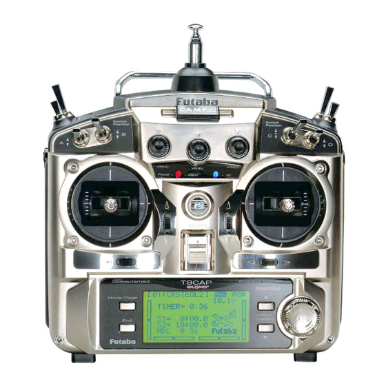
TRANSMITTER CONTROLS - AIRPLANE Be careful not to bend your antenna when you Antenna collapse or extend it. CAMPac or Dust Cap Antenna must be fully extended when flying. VR(B) VR(A) CH8 Knob Carrying Handle Flap Trim Control This controls CH6, and if flaperon mixing VR(C) is activated controls the flap. - Page 12 TRANSMITTER CONTROLS - HELI Be careful not to bend your antenna when you Antenna collapse or extend it. CAMPac or Dust Cap Antenna must be fully extended when flying. VR(B) VR(A) CH8 Knob Carrying Handle Hovering - Pitch Knob VR(C) Hovering - Throttle Knob SW(B) Rudder Dual Rate Switch...
- Page 13 To remove, press the tabs together and gently pull rearwards. To install, line up the connector pins with the socket in the rear of the module and gently snap into position. RF module Trainer function /DSC function connector Ni-Cd battery pack NOTE: If you need to remove or replace the transmitter battery, do not pull on its wires to remove it.
-
Page 14: Charging The Ni-Cd Batteries
RECEIVER AND SERVO CONNECTIONS Receiver Aircraft (ACRO) Helicopter (HELI) Output and Glider (GLID1FLAP/GLID2FLAP/GLID2FL-C) Channel ailerons/right aileron /combined right flap & aileron aileron (cyclic roll) elevator elevator (cyclic pitch) throttle throttle rudder rudder spare/landing gear/left aileron /combined left flap and spare/gyro aileron right flap (GLD2FLAP/GLID2FL-C) spare/ flap(s)/combined left flap and aileron... -
Page 15: Adjusting Display Contrast
Adjusting the length of the non-slip control sticks You may change the length of the control sticks to make your transmitter more Stick tip A Locking piece B comfortable to hold and operate. To lengthen or shorten your transmitter’s sticks, first unlock the stick tip by holding locking piece B and turning stick tip A counterclockwise. - Page 16 Always use an extension of the proper length. Avoid plugging multiple extensions together to attain your desired length. If distance is greater than 18” or multiple or high current draw servos are being used, use Futaba Heavy-Duty servo exten- sions.
-
Page 17: Aircraft Frequencies
This is a brief explanation of range test. For more in-depth specifics on receiver antenna mounting, additional checks if unsatisfactory rage is demonstrated, range checking with gasoline powered engines, etc, please see our F.A.Q. page at www.futaba-rc.com. • Leave the transmitter's antenna retracted and be sure both batteries are fully charged. -
Page 18: Transmitter Displays And Buttons
TRANSMITTER DISPLAYS & BUTTONS When you first turn on your transmitter, a confirmation double beep sounds, and the screen shown below appears. Before flying, or even starting the engine, be sure that the model type and name appearing on the display matches the model that you are about to fly! If you are in the wrong model memory, servos may be reversed, and travels and trims will be wrong, leading to an immediate crash. -
Page 19: Warning And Error Displays
[Note] At this warning display, the transmitter transmits in PPM mode even if the set-up mode is PCM mode. Do not fly when this message is displayed — all programming has been erased and is not avail- able. Return your transmitter to Futaba for service. MEMORY MODULE INITIALIZE DISPLAY This warning appears when an (optional) CAMPac memory module is used in the transmitter for the first time. -
Page 20: Quick Guide To Setting Up A 4-Channel Airplane
AIRCRAFT (ACRO) MENU FUNCTIONS Please note that all BASIC menu functions are the same for airplanes (ACRO), sailplanes (GLID1FLAP/2FLAP/2FL-C), and helicopters (HELISWH1/SWH2/SWH4/SR-3/SN-3/SR-3s). The glider BASIC menu does not include IDLE-DOWN or THR-CUT; the helicopter BASIC menu includes additional features (swashplate adjustment and throttle/pitch curves and revo for Normal flight mode) that are discussed in the Helicopter section. -
Page 21: Map Of Acro Basic Functions
MAP OF ACRO BASIC FUNCTIONS (Startup screen) Mode/Page To enter the Basic Menu, press the To return to the Startup screen, press the Mode key for one second. End key. ( for one second) ACRO Basic Menu (Basic Menu 1/2) (Basic Menu 2/2) Mode/Page Select... -
Page 22: Servo Reverse
A QUICK GUIDE: GETTING STARTED WITH A BASIC 4-CHANNEL AIRCRAFT This guide is intended to help you get acquainted with the radio, to give you a jump start on using your new radio, and to give you some ideas and direction in how to do even more than you may have already considered. It follows our basic format of all programming pages: a big picture overview of what we accomplish;... -
Page 23: Dual/Triple Rates And Exponential (D/R, Exp)
With digital trims you don’t shut the engine off with . Let's set up IDLE-DOWN and “throttle cut” (THR-CUT) now. THROTTLE TRIM GOALS of EXAMPLE STEPS INPUTS for EXAMPLE Set up IDLE-DOWN. From the BASIC menu, choose IDLE-DOWN. 5 steps to IDLE-DOWN. P. -
Page 24: Trainer
GOALS of EXAMPLE STEPS INPUTS for EXAMPLE Set the second (low) rate throws and A to down position. exponential. to D/R. Repeat steps above to set low rate. Optional: change dual rate switch to SW. to G or E. assignment. Ex: elevator to switch G G or E to center position. - Page 25 A LOOK AT THE RADIO'S FUNCTIONS STEP BY STEP MODEL submenu: includes three functions that manage model memory: MODEL SELECT, MODEL COPY and MODEL NAME. Since these functions are all related, and are all basic features used with most models, they are together in the MODEL submenu of the BASIC menu.
- Page 26 MODEL COPY: copies the current model data into another model memory (in the transmitter or the optional DP-16K CAMPac). The name of the model memory you are copying into is displayed for clarity. Notes: • Any data in the model copied to will be written over and lost, including name, type and modulation.
- Page 27 MODEL NAME: assigns a name to the current model memory. By giving each model a name that is immediately recognizable, you can quickly select the correct model, and minimize the chance of flying the wrong model memory which could lead to a crash. Adjustability and values: •...
- Page 28 PARAMETER submenu: sets those parameters you would likely set once, and then not disturb again. Once you have selected the correct model you wish to work with, the next step is setting up the proper parameters for this specific model: •...
- Page 29 MODEL TYPE: sets the type of programming used for this model. The 9C super has 12 model memories, which can each support: • one powered aircraft (ACRO) memory type (with multiple wing and tail configurations. See twin aileron servos, twin elevator servos, ELEVON, and V-TAIL for further information.);...
- Page 30 PCM = Pulse Code Modulation PPM = Pulse Position Modulation (also called FM). Adjustability: • PCM setting for all Futaba PCM1024 receivers, regardless of number of channels (ie. R138DP/148DP/149DP, R309DPS); • PPM setting for all Futaba compatible (negative shift) FM receivers, regardless of number of channels (ie.
- Page 31 Adjustable travel limit (ATL): makes the channel 3 ) effective only at low throttle, disabling the trim TRIM LEVER HROTTLE at high throttle. This prevents pushrod jamming due to idling trim changes. This function defaults to ON. If you are not using channel 3 for throttle, you may want trim operation the same as on all other channels.
- Page 32 End Point of servo travel adjustment (END POINT, also called EPA): the most flexible version of travel adjustment available. It independently adjusts each end of each individual servo’s travel, rather than one setting for the servo that affects both directions. Again, for CCPM helicopters, be sure to see SWASH AFR (see p. 84) prior to adjusting end points. Adjustability: •...
- Page 33 Engine idle management: IDLE-DOWN and THR-CUT: functions which work with the digital T to provide a HROTTLE simple, consistent means of engine operation. No more fussing with getting trim in just the right spot for landings or take offs! For additional engine adjustments, see THROTTLE-NEEDLE (p. 58) and THROTTLE DELAY (p. 59). IDLE-DOWN (ACRO only): lowers the engine idle for: sitting on the runway prior to take off, stalls and spins, and landings.
- Page 34 Throttle cut (THR-CUT) (ACRO/HELI): provides an easy way to stop the engine by flipping a switch (with T HROTTLE TICK at idle). The movement is largest at idle and disappears at high throttle to avoid accidental dead sticks. In HELI, there is an additional setting, THR.
- Page 35 Dual/triple rates and exponential (D/R,EXP): assigns adjusted rates and exponential. Dual/Triple Rates: reduce/increase the servo travel by flipping a switch, or (ACRO/ GLIDER) they can be engaged by any stick position. Dual rates affect the control listed, such as aileron, not just a single (ex: channel 1) servo. For example, adjusting aileron dual rate will affect both aileron servos when using FLAPERON or AIL-DIF, and both aile- ron and elevator servos’...
- Page 36 Adjustability: • More sensitive around neutral. (positive exponential, see example) • Less sensitive around neutral. (negative exponential, see example) • Adjustable for each direction. (ACRO/GLIDER) For throttle, exponential is applied at the low end to help nitro and gasoline engines have a linear throttle response, so that each 1/4 stick increases engine RPM 25% of the available range.
- Page 37 Adjust the sensitivity of the trims: see p. 41. Set up twin aileron servos: see p. 44. Set up twin elevator servos: see p. 50. Set up programmable mixes to meet your specific needs: see p. 54. www.futaba-rc.com\faq\faq-9c.html for all triple rates on a single switch, etc.
-
Page 38: Timer Submenu
TIMERsubmenu (stopwatch functions): controls three electronic clocks used to keep track of time remaining in a competition time allowed, flying time on a tank of fuel, amount of time on a battery, etc. Adjustability: • Count down timer: starts from the chosen time, displays time remaining. If the time is exceeded, it continues to count below 0. - Page 39 Auxiliary channel function (including channel 9 controls) (AUX-CH): defines the relationship between the transmitter controls and the receiver output for channels 5-9. Also, the CH9 SERVO REVERSE is used to change the CH9 servo direction. Note that the CH9 functions are only visible in the AUX-CH screen when PCM modulation is selected. The 9th channel is not supported in FM modulation.
-
Page 40: Trainer
WITCH • Compatibility: The 9C super may be master or student with any Futaba FM transmitter compatible with the cord. Simply plug the optional trainer cord (For 9C series, sold separately) into the trainer connection on each transmitter, and follow the guidelines below Examples: •... - Page 41 TRIM submenu: resets and adjust effectiveness of digital trims. The 9CA super has digital trims which are different from conventional mechanical trim sliders. Each T is actually a two-direction switch. Each time the T EVER EVER pressed, the trim is changed a selected amount. When you hold the T , the trim EVER speed increases.
-
Page 42: Servo Display
SUB-TRIM: makes small changes or corrections to the neutral position of each servo. Range is -120 to +120, with 0 setting, the default, being no SUB-TRIM. We recommend that you center the digital trims before making SUB-TRIM changes, and that you try to keep all of the SUB-TRIM values as small as possible. - Page 43 FailSafe (loss of clean signal and low receiver battery) submenu (PCM mode only) (F/S): sets responses in case of loss of signal or low Rx battery. FailSafe (F/S): instructs a PCM receiver what to do in the event radio interference is received. Adjustability: •...
-
Page 44: Acro Advance Menu Functions
(For details on setting up a complex aerobatic plane, such as one with 4 wing servos using full span ailerons and full span flaps, as well as AIRBRAKE/crow and other features, please visit our FAQ at www.futaba-rc.com\faq\faq-9c.html. Many other setup examples are also available at this location.) NOTE: Only one of the three wing-type functions (FLAPERON, AIL-DIFF, and ELEVON) can be used at a time. -
Page 45: Flap Trim
Mix flaperon's flap motion to another inboard flap (plugged into aux1): see p. 54. View additional model setups on the internet: www.futaba-rc.com/faq/faq-9c.html * If you receive an error message that OTHER WING MIXING IS ON, you must deactivate AIL-DIFF or ELEVON . see p. 44. - Page 46 Adjust individual servo's SUB-TRIMs: see p. 42 and END POINTs: see p. 32. Where next? Set up AIRBRAKE mix: see p. 56 and ELEV-FLAP mix: see p. 55. Mix flaperon's flap movement to an additional inboard flap (plugged into aux1): see p. 54. View additional model setups on the internet: www.futaba-rc.com\faq\faq-9c.html.
-
Page 47: Aileron Differential (Ail-Diff)
Set up ELEV-FLAP mix (only if model has a flap servo in CH6): see p. 55. Set up SNAP-ROLL Function: see p. 52. View additional model setups: www.futaba-rc.com\faq\faq-9c.html. *If you receive an error message that OTHER WING MIXING IS ON, you must deactivate ELEVON or FLAPERON. See p. 44. - Page 48 Allows twin aileron servo operation Select AIL-2 and change to CH5&6. to CH5&6. with a 5-channel receiver. Close menu. Finish setting up FLAPERON or AIL-DIFF. see Twin Aileron Servos: p. 44. Where next? View additional model setups on the internet: www.futaba-rc.com\faq\faq-9c.html.
-
Page 49: Elevon
ILERON LEVATOR TICKS (For details on setting up a complex aerobatic plane, such as "space shuttle" style controls, please visit www.futaba-rc.com\faq\faq-9c.html. Many other setup examples are also available at this location.) GOAL of EXAMPLE: STEPS: INPUTS: Activate ELEVON. -
Page 50: Twin Elevator Servos (Ailevator)
• CH2 and CH8 only. (With programmable mixing, could utilize CH5 as the 2nd elevator servo. for examples.) THROTTLE-NEEDLE uses CH8 and cannot be active simultaneously. www.futaba-rc.com\faq\faq-9c.html • Direction of each servo's travel may be reversed in REVERSE or the set percentages may be reversed here. -
Page 51: V-Tail
PROG.MIX, p. 60.) (For details on setting up a complex plane, such as one with a v-tail AND a separate steerable nosewheel, please visit our FAQ at www.futaba-rc.com\faq\faq-9c.html. Many other setup examples are also available at this location.) GOAL of EXAMPLE:... -
Page 52: Snap Roll
Snap Rolls at the flick of a switch (SNAP-ROLL) (ACRO/GLID): This function allows you to execute snap rolls by flipping a switch, providing the same input every time. It also removes the need to change dual rates on the 3 channels prior to performing a snap, as SNAP-ROLL always takes the servos to the same position, regardless of dual rates, inputs held during the snap, etc. - Page 53 (Ex: Change to the left/down to B. snap and adjust rudder to 105%.) A down B down. Repeat steps above to set percentages. Close menu. Where next? Set up programmable mixes: see p. 54. View additional setups on the internet: www.futaba-rc.com\faq\faq-9c.html.
- Page 54 • THROTTLE DELAY mixing is a pre-programmed delay mix that slows down the response of the CH3 servo. (see p. 59.) Next, we'll get an in-depth look at some pre-programmed mixes (mixes whose channels are predefined by Futaba for simplicity) we’ve not covered yet, and last, look at the fully-programmable mix types.
-
Page 55: Elev-Flap
45%. LEVATOR TICK Close menu. Adjust flaperons' flap travel available (FLAPERON): see p. 45. Where next? Set up AIRBRAKE (crow/butterfly): see p. 56. Set up programmable mixes (ex: FLAP-ELEVATOR): see p. 60. View additional setups on the internet: www.futaba-rc.com\faq\faq-9c.html. - Page 56 AIRBRAKE/BUTTERFLY(crow) mixing (ACRO/GLID): Like FLAPERON and AILEVATOR, AIRBRAKE is one function that is really made up of a series of pre-programmed mixes all done for you within the radio. AIRBRAKE(often called "crow" or BUTTERFLY - see GLID, p. 71 for details) simultaneously moves the flap(s) (if installed), twin ailerons (if installed) and elevator(s), and is usually used to make steep descents or to limit increases in airspeed in dives.
- Page 57 Close menu. Where next? Adjust flaperons' total flap travel available (FLAPERON): see p. 45. Set up ELEV-FLAP mixing: see p. 55. Set up programmable mixes, for example, FLAP-ELEVATOR: see p. 60. View additional model setups on the internet: www.futaba-rc.com\faq\faq-9c.html.
-
Page 58: Throttle-Needle
Where next? Set up THROTTLE DELAY to imitate a jet engine’s lag: see p. 59. Adjust throttle and Ch8 END POINTs: see p. 32. Set up programmable mixes, for example, AILERON-to-RUDDER: see p. 60. View additional model setups on the www.futaba-rc.com\faq\faq-9c.html. -
Page 59: Throttle Delay
This function may also be used to create a “slowed servo” on a channel other than throttle. This is accomplished by plugging the desired servo (Ex: gear doors) into CH3 (THR), throttle into an auxiliary channel such as 8, and then using some creative mixes. Please see our Frequently Asked Questions area at www.futaba-rc.com\faq\faq-9c.html for this specific example. GOAL of EXAMPLE:... - Page 60 LINEAR PROGRAMMABLE MIXES (PROG.MIX1-5): Your 9C super contains five separate linear programmable mixes (ACRO and GLID. HELI has 2). (Note that mixer #6-7’s mixing RATEs are set with a 5-point curve. see CURVE MIXES, p. 63.) There are a variety of reasons you might want to use these mixes. A few are listed here. All of the adjustable parameters are listed below, but don’t let them scare you.
- Page 61 • Dial as master: To directly effect one servo’s position by moving a dial, set the master as the desired dial. (Ex: create a second throttle trim on left slider.) MASTER SLAVE LINK TRIM SWITCH POSITION RATE OFFSET VR(D) THRO NULL •...
- Page 62 Set up additional programmable mixes, ex: RUDDER-AILERON: see p. 60. View numerous additional mix setups: www.futaba-rc.com\faq\faq-9c.html. Other Examples: • RUD-THR (HELI) mix: When right rudder is applied, additional torque is needed from the motor to drive the tail left. Left rudder requires less torque.
- Page 63 CURVE PROGRAMMABLE MIXES (PROG.MIX6, PROG.MIX7): Your 9C super’s ACRO/GLID programs contain two separate curve programmable mixes. HELI contains one. There are a variety of reasons you might want curve mixes — usually where a linear mix doesn’t fit your needs along the whole range. One pre-programmed curve mix is the THROTTLE-NEEDLE function.
- Page 64 Adjust servo END POINTs: see p. 32. Set up AILEVATOR: see p. 50. Set up linear programmable mixes, ex: RUDDER-to-Aux2 (twin rudder servos): see p. 60, or additional curve mix, ex: RUDDER-AILERON: see p. 63. View numerous mix setups: www.futaba-rc.com\faq\faq-9c.html...
-
Page 65: Gya Gyro Mixing (Gyro Sense)
GYA gyro mixing GYA series gyros: GYA series gyros are a high performance, compact, and light weight AVCS gyro developed for model airplane. Integrated sensor and control circuit make it easy to mount. • GYA350: for airplane aileron, elevator, or rudder. GYA351: for airplane ailerons, especially two servos such as when using FLAPERON. - Page 66 95. For aerobatics, gyros on rudder and elevator fix over-rotation of snaps and spins as well as tail wagging in stall turns. (Futaba offers a twin-axis gyro, GYA-352, that controls two axes with a single gyro.) For 3D aerobatics (below stall speed, such as torque rolls), heading-hold/AVCS gyros on rudder and elevator dramatically simplify these maneuvers.
-
Page 67: Model Type (Parameters Submenu)
GLIDER MODEL FUNCTIONS Please note that nearly all of the BASICmenu functions are the same for airplane (ACRO setup), sailplane (GLID1FLAP/ 2FLAP/2FL-C setups), and helicopter (HELISWH1/SWH2/SWH4/SR-3/SN-3/SR-3s setups). The features that are identical refer back to the ACRO chapter. The glider BASIC menu does not include IDLE-DOWN or THR-CUT. Note that in all cases where ACRO programming labels channel 3 as throttle, GLID programming labels channel 3 as ARB (airbrake), since airbrakes are normally operated on channel 3 in gliders. - Page 68 GETTING STARTED WITH A BASIC 4-CHANNEL (Aileron/Flap/Rudder/Elevator) GLIDER This guideline is intended to help you get acquainted with the radio, to give you a jump start on using your new radio, and to give you some ideas and direction in how to do even more with this powerful system than you may have already considered.
- Page 69 GOAL of EXAMPLE: STEPS: INPUTS: Adjust travels as needed to match In the BASIC menu, choose END POINT. 2 steps to END POINT. model’s recommended throws (usually to choose END POINT. listed as high rates). P. 32. Adjust the servos’ end points. to FLAP.
- Page 70 A LOOK AT THE RADIO'S GLID-SPECIFIC FUNCTIONS STEP BY STEP. Those functions which are identical to the ACRO setups are referred directly to those pages. MODEL TYPE: This function of the PARAMETER submenu is used to select the type of model programming to be used. GLIDER TYPES: Glider1FLAP Configuration Glider2FLAP/2FL-C Configuration...
- Page 71 GLIDER ADVANCE MENU Varied wing types and tail types (twin aileron servos, twin elevator servos, elevon, v-tail, etc). See p. 44-51 for basic information. • FLAPERON (GLID1FLAP only): 2 aileron servos operate in opposite directions as ailerons and same direction as flaps. See p. 45. •...
- Page 72 C. to CENTER. Close. Where next? ELEV-FLAP mixing. See p. 55. BUTTERFLY. See p. 56. Use a mix to OFFSET the flaps a set distance on a specified switch: see p. 60. View additional model setups on the internet: www.futaba-rc.com\faq\faq-9c.html...
- Page 73 4 wing servos in flight. Close the function. Where next? SPEED OFS mixing. See p. 74. BUTTERFLY. See p. 56. Create a programmable mix to meet your model' s setups: see p. 60. View additional model setups on the internet: www.futaba-rc.com\faq\faq-9c.html.
- Page 74 4 wing servos in flight. Close the function. START OFS mixing. See p. 73. Where next? BUTTERFLY. See p. 56. Create a programmable mix to meet your model' s setups: see p. 60. View additional model setups on the internet: www.futaba-rc.com\faq\faq-9c.html.
- Page 75 FLP1 and 2, 100%, ELEV -5%.) (9CAS=G, 9CHS=E.) WITCH to -5%. to ELEV. Note: switch is assignable. (SW/MODE) Repeat for, FLP1 and 2, AIL2. (null) Close the function. Note: knob is assignable. (CAMBER) Where next? View additional model setups on the internet: www.futaba-rc.com\faq\faq-9c.html.
- Page 76 BUTTERFLY (crow) mixing (GLID2FL-C): BUTTERFLY (often called "crow" - see GLID, p. 71 for details) simultaneously moves the flap, twin ailerons and elevator, and is usually used to make steep descents or to limit increases in airspeed in dives. Adjustability: •...
-
Page 77: Channel 3'S Function Selection (Sw/Mode)
Close menu. B.FLY-ELE. Mix switch is selectable in the SW/MODE. Where next? View additional model setups on the internet: www.futaba-rc.com\faq\faq-9c.html. Channel 3's function selection (SW/MODE): (GLID1FLAP/GLID2FLAP) (GLID2FL-C) Channnel 3's function is selectable in the ARBK-FUNC item. (Throttle stick, switches, or knobs) By choosing except STK, channel 3's function may be separated from BUTTERFLY's function, so channel 3 can be used for other functions. -
Page 78: Swash-Thr (Swash To Throttle Mixing) (Not In Swh1)
HELICOPTER MODEL FUNCTIONS Please note that nearly all of the BASIC menu functions are the same for airplane (ACRO setup), sailplane (GLID1FLAP/ 2FLAP/2FL-C setups), and helicopter (HELISWH1/SWH2/SWH4/SR-3/SN-3/SR-3s) setups. The features that are identical refer back to the ACRO chapter. The Helicopter BASIC menu includes the normal conditionís throttle and collective pitch curves and revo. -
Page 79: Helicopter (Sw
GETTING STARTED WITH A BASIC HELICOPTER This guideline is intended to help you set up a basic (SWH1) heli, to get acquainted with the radio, to give you a jump start on using your new radio, and to give you some ideas and direction on how to do even more with this powerful system than you may have already considered. - Page 80 Reverse servos as needed for proper In the BASIC menu, open REVERSE. 4 steps to REVERSE. control operation. Ex: L UDDER to choose REVERSE. results in leading edge of tail TICK rotor blades moving left. Reverse to Choose desired servo and reverse its to CH4: RUDD.
- Page 81 Learn how to operate HOVERING PITCH Notice at half throttle, the VR(C) dial for 1 second. (If ADVANCE, again.) and HOVERING THROTTLE. See p. 93. adjusts the throttle separately from the 1 step to SERVO. pitch. VR(A) adjusts the pitch separately from the throttle.
-
Page 82: Heli-Specific Basic Menu Functions
Additionally, different angles of CCPM may also be created utilizing the fully assignable programmable mixes. (See our Frequently Asked Questions area at www.futaba-rc.com\faq\faq-9c.html for specific examples.) Not operating quite like you expected? In many CCPM installations you need to either reverse the direction of a specific function (SWASH AFR) or reverse a single servoís direction (REVERSE). -
Page 83: Model Type (Parameters Submenu)
GOAL of EXAMPLE: STEPS: INPUTS: Change the MODEL TYPE of model #3 Confirm you are currently using the On home screen, check model name from aircraft to 120 degree CCPM with 2 proper model memory. (example: 3) and # on top left. If it is not the correct model (example: servos working in unison for collective 3), see MODEL SELECT, p. -
Page 84: Swash Afr
SWASH AFR (not in SWH1): Swashplate function rate settings (SWASH AFR) reduce/increase/reverse the rate (travel) of the aileron, elevator (except SWH2 ) and collective pitch functions, adjusting or reversing the motion of all servos involved in that function, only when using that function. - Page 85 Swash to Throttle Mixing (SWASH-THR): This function can be set for each flight condition, and is used to correct the tendency of the model to change altitude when the rotor is tilted by aileron, elevator, and other controls. Adjustability: • Mixing may be set from 0 to 100% each flight condition. GOAL of EXAMPLE: STEPS: INPUTS:...
-
Page 86: Setting Up The Normal Flight Condition
Setting up the Normal Flight Condition: The Normal flight condition is typically utilized for hovering. The throttle and collective pitch curves are adjusted to provide consistent engine RPM despite the increase/decrease in collective pitch of the blades. This keeps the engine from “bogging down” under excessive load (like trying to accelerate a car on a steep hill in 5th gear) or excessive RPM under insufficient load (like flooring the throttle while in neutral), risking engine damage. - Page 87 GOAL of EXAMPLE: STEPS: INPUTS: Set up Normal Flight Condition Open the THR-CV/NOR function. for 1 second. (If ADVANCE, again.) Throttle/Collective Pitch Curves to THR-CV/NOR. and Revo. Adjust the first point. (Ex: 5%.) Base point: Adjust base point of to 5%. throttle curve until engine idles Open the PIT-CV/NOR function.
-
Page 88: Heli-Specific Advance Menu Functions
HELI-SPECIFIC ADVANCE MENU FUNCTIONS THR-HOLD: This function holds the engine in the idling position and disengages it from the T when S HROTTLE TICK WITCH E (9CH) or G (9CA) is moved. It is commonly used to practice auto-rotation. Prior to setting up THR-HOLD, hook up the throttle linkage so that the carburetor is opened fully at high throttle, then use the digital trim to adjust the engine idle position. -
Page 89: Throttle Hold
THR-CURVE and PIT-CURVE: These 5-point curves are utilized to best match the blade collective pitch to the engine RPM for consistent load on the engine. Curves are separately adjustable for normal, idle-up 1, idle-up 2, and idle-up 3. In addition, a separate collective pitch curve is available for throttle hold. - Page 90 Revo. mixing rates are 5-point curves. For a clockwise-turning rotor, the rudder is mixed in the clockwise direction when collective pitch is increased; for counterclockwise-turning, the opposite. Change the operating direction setting by changing the signs of the numbers in the curve from plus (+) to minus (-) and vice versa. Suggested defaults: Clockwise rotation: -20, -10, 0, +10, +20% from low throttle to high.
-
Page 91: Idle-Ups
OFFSET: Optional separate trims in addition to those for the normal condition. This function is used to automatically change the trim of a helicopter, for example, when transitioned from hover to flying at high speed. A clockwise-rotation rotor helicopter tends to drift to the right at high speed, so an aileron offset may be applied to offset the helicopter to the left. The necessary elevator offset varies with model geometry, so it must be determined by noting collective pitch changes at high speed. - Page 92 DELAY: The Delay function provides a smooth transition between the trim positions whenever OFFSET, REVO. MIXING, or THROTTLE HOLD functions are turned on and off. Adjustability: • Separate delay times are available for aileron, elevator, rudder, throttle, and pitch. • With a 50% delay setting, the servo takes about a half-second to move to its new position...quite a long time. •...
- Page 93 HOVERING ADJUSTMENTS (HOV-THR and HOV-PIT): Hovering throttle and hovering pitch are fine-tuning adjustments for the throttle and collective pitch curves individually, affecting performance only around the center point and only in the normal condition. They allow in-flight tweaking of the curves for ideal setup.
-
Page 94: High/Low Pitch
HIGH/LOW PITCH (HI/LO-PIT): This function may be used to adjust the curves high and low side individually for each flight condition (normal, idle-up 1, idle-up 2, idle-up 3, throttle hold). Adjustability: • You may define high and low side rate trim knobs (the high side pitch trim control is defined as the right side lever at initial setting). -
Page 95: Gyros And Governors
As you ease off the rudder, the gain increases again, minimizing tail wag and keeping the model straight. (If your gyro does not include stick priority, you can manually create it. Please see www.futaba-rc.com\faq\faq-9c.html.) Choosing the right gyro for your skills, your helicopter, and your budget: •... - Page 96 Gain Example for AVCS/Heading-hold Gyros (GY) 100% NOR 100% AVC "Normal Mode" "Heading Hold Mode" -100% +100% GOAL of EXAMPLE: STEPS: INPUTS: Set up a heading-hold/AVCS gyro with Open and activate the GYRO function. for 1 second. (If basic, again.) heading-hold/AVCS setting in idle-ups to GYRO.
- Page 97 GOVERNORS: GV-1 connections Magnetic sensor Throttle servo Control amp Mixture servo Connected only when fuel mixture function used. Speed setting channel Throttle channel Connected when speed set from transmitter Governor ON/OFF / Mixture trim channel Connected when the governor is turned on and off from transmitter and when mixture trim function is used, or when mixture curve data is sent from transmit- ter to governor...
- Page 98 • In-flight adjustment of the head speed (for easy adjustment during tuning) may be created using an additional channel and a programmable mix. See www.futaba-rc.com\faq\faq-9c.html for details. The GV-1 controls throttle when it is active, so the throttle will not obey any FailSafe settings preset for throttle in the transmitter.
- Page 99 GOAL of EXAMPLE: STEPS: INPUTS: Set up a GV1 governor to use both Open and activate the GOVERNOR for 1 second. (If basic, again.) channels into the receiver and switch function. to GOVERNOR. between the governor settings automatically when changing conditions. to ACT.
-
Page 100: Glossary
GLOSSARY 3D: Common name for certain types of aerobatic maneuvers. Aircraft: flying below the model’s stall speed, such as torque rolls. Helicopters: combining 2 or more maneuvers, such as rolling loop. 4.8V: 4.8 volt battery pack, made of 4 Ni-Cd 1.2V cells. See Accessories. 5-cell: 6.0 volt battery pack, made of 4 alkaline cells or 5 Ni-Cd cells. - Page 101 CAMPac: Optional extended data storage module. Futaba stock # DP16K....... .
- Page 102 Copy model: see MODEL COPY. Crow: see BUTTERFLY (GLID) and AIRBRAKE (ACRO). Cursor: See S ELECT UTTONS Curve Mix: a mix that does not have the same reaction at all points along the master channel. See Programmable mix. Cyclic: horizontal controls on a helicopter. Cyclic pitch is typically called elevator. Cyclic roll is typically called aileron. Data reset: erase all data in a specific model.
- Page 103 Elevator-to-pitch mix: (HELI) used to adjust pitch to counter the loss of angle of attack when elevator input is given. Not a preprogrammed mix. See Programmable mix. This is the default setting of one mix in HELI. ELEVON: flying wing configuration with 2 servos working together to create both aileron and elevator action. See Twin elevator servos.
- Page 104 GOVERNOR: (HELI) programming which eases the setup of the GV-1 governor.......95 GV-1: part number/name for Futabaís electronic governor. See Gyros and Governors and GOVERNOR for details.
- Page 105 TP75FM for ground use, 75MHz............9 Name: see MODEL NAME. Neckstrap: optional strap to suspend transmitter during use. Futaba stock # FTA8. See Accessories.
- Page 106 Ni-Cd: Nickel Cadmium rechargeable battery. Typically used to power transmitter and receiver. See Battery care and charging. NiMH: Nickel Metal Hydride rechargeable battery. Newer battery technology than Ni-Cd. Longer run times but more specific peak charging requirements. [Require a (zero) delta peak charger labeled specifically for use with NiMH batteries.] NORMAL: trainer mode that does not give student radio the computer programming features of the master radio.
- Page 107 See AUX-CH. Synthesized module/receiver: The 9C super's compatible with the R309DPS Futaba synthesized receiver that can be used on any 72MHz channel. There is not a synthesized transmitter module that is safe/FCC certified/approved for use with the...
- Page 108 THR-DELAY: (ACRO) throttle delay, slows engine servo response to imitate the spool-up action of a turbine engine. May also be used creatively to create a delayed servo on a different function (see www.futaba-rc.com\faq\faq-9c.html.) ..59 THR-REV: reverses the throttle trim function to the top of the T .
- Page 109 Warranty information................3 Website: www.futaba-rc.com. Internet location of extensive technical information Futaba products....3...
Need help?
Do you have a question about the 9 CHP SUPER and is the answer not in the manual?
Questions and answers