Table of Contents
Advertisement
Advertisement
Table of Contents

Related Manuals for FUTABA 9VAP


Summary of Contents for FUTABA 9VAP
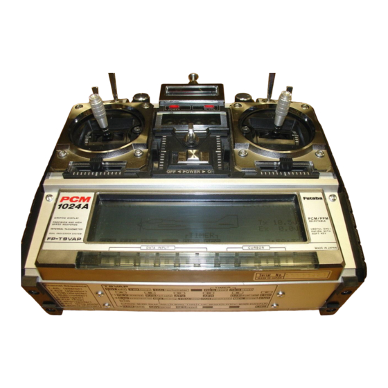
- Page 1 Futaba DIGITAL PROPORTIONAL RADIO CONTROL PCM 1024A PULSE CODE MODULATION SYSTEM...
-
Page 2: Table Of Contents
SOFT MAP 2 ..... . . 56 WARNING: The FUTABA PCM1024A system has numerous operating features and is designed for serious and experienced radio con- trol hobbyists. Newcomers to the hobby should seek advice and assistance in operating this set. Improper operation can result in property damage and/or serious personal injury. -
Page 3: Features
•FEATURES The PCM1024A was specially-developed to meet the needs of the serious and demanding R/C hobbyist. Numerous features make this system adaptable to a wide variety of complex radio control stunt and scale aircraft. This is the most advanced system available for FAI Precision Acrobatic (F3A) competition. - Page 4 • Fiberglass reinforced epoxy resin PC board vibration and shock resistance and neutral with thru-the-hole plating improves reliability precision tremendously. against shock and vibration. • Futaba custom provides high starting • Seven special adjustable splined output arms.
-
Page 5: Set Contents
•SET CONTENTS Model FP-9VAP Transmitter FP-T9VAP x 1 Receiver FP-R129DPx 1 Servos FP-S9101 x 4 , o r S 5 1 0 1 x 4 Switch SSW-J x 1 Nicd Battery NR-4J x 1 Battery charger, extension cord, DSC cord, CHG adaptor, DSC-CHG cord, Misc. -
Page 6: R E C E I V E R And Servos
•RECEIVERS AND SERVOS Receiver, servo, switch, and battery connections Pitch Control Servo Spoiler Servo Pay careful attention to the Flap Servo polarity of the connectors. Receiver Crystal Lighter-shaded parts must be purchased separately. Landing Gear Servo Antenna Wire Rudder Servo PCM Receiver Five servos R129DP... - Page 7 • The crystal can be changed without opening that each servo follows its control stick move- the receiver case. Always use a Futaba matched ment. TX/RX crystal set to change frequencies.
-
Page 8: Nicd B A T T E R Y Charging
BATTERY CHARGING INSTRUCTIONS (Transmitter and Receiver Nicd Batteries) Before operating your system, recharge the Nicd batteries as follows: then charge it a full 15 hours. •Connect the DIN connector of the FBC-8B (2) •The amount of time remaining before the bat- battery charger to the transmitter charging teries must be recharged can be estimated by socket, and connect the 3P connector to the... -
Page 9: Basic T R A N S M I T T E R T9Vap Control
•BASIC TRANSMITTER T9VAP CONTROLS. Refer to the fold-out illustration in the back of the manual. 1. Aileron Non-slip Adjustable Control Sticks 2. Elevator The length of the control sticks can be adjusted 3. Throttle to suit operator preference. 4. Rudder 5. - Page 10 Mini Stand Opening Trimmer Panel and Key Cover Use this fold-out Mini Stand as shown when lay- ing the transmitter down. This makes operation Flip up with easier and protects the transmitter and module. the tab NOTE: Flip up at both sides with your fingers.
- Page 11 Monitor Lamps 4. ELE.D/R Elevator Dual Rate throw adjustment (This trimmer is ineffective if ELV D/R is not set to ACT) See D/R instructions page 5. ELE.AFR.UP Elevator up endpoint adjust- ment. 6. ELE.AFR.DN Elevator down endopoint adjustment. 7 . 6 - > 2MIX FLP. Airbrake Mixing Flap ad- justment.
-
Page 12: Operating Instructions
ADJUSTMENTS AND FLIGHT TECHNIQUES •OPERATING INSTRUCTIONS. • When adjusting and setting the transmitter functions, connect the receiver and servos, and make the adjustments while observing the operation of the servos. • Alternatively, when studying the operation of transmitter functions, remove the transmit- ter RF module (to reduce battery drain). - Page 13 Setting Instructions 1) Display the standard screen. 2) Reset the Total Timer by pressing the two program keys simultaneously. RES 3) Press the key. The TIMER program screen will appear on the display. The Up Timer will be dis- played first. 4) Select the UP (Up), DN (Down), or RYT (Rhythmic) timer mode by pressing the , or program key.
-
Page 14: Tachometer
'ADJUSTMENTS AND FLIGHT TECHNIQUES TACHO METER Tachometer The tachometer function is used to measure the speed on one to five-bladed propellers, etc. Speed (rpm) is measured up to a maximum of 50,000 rpm (in 20 rpm increments). Setting Method 1) Display the standard screen, and press the side panel) at the front or rear of the propeller TAC program key. -
Page 15: Back-Up Warning
When the power switch is turned on the system. To locate the cause, call your Futaba service center. The back up lithium battery life again, the error display disappears and all the depends on the usage state, but is about 5 years. -
Page 16: Reverse
ADJUSTMENTS AND FLIGHT TECHNIQUES REVERSE Servo Reversing This function is used to change the direction of servo operation in relation to control stick or lever movement. Setting Method 1) Select the EDIT screen, the select the RE- pressing the NOR or REV program key. VERSE screen by pressing the REV program In the display example, RUD (Rudder) is set key. - Page 17 Battery Fail Safe Setting Fail Safe and Hold General Instructions 1) Set the Failsafe position on the throttle chan- Fail Safe nel (CH3) as described above. A position • F/S or HOLD can be selected for each channel slightly above the minimum engine idle speed (1 to 8).
-
Page 18: Adjustable T R A V E L Volume (Atv)
ADJUSTMENTS AND FLIGHT TECHNIQUES ADJUSTABLE TRAVEL VOLUME • The ATV function is used to adjust servo travel limits. Servo travel can be adjusted independently in each direction from neutral. Adjustment from 30% to 110% of normal full travel (throw) is possible. •... -
Page 19: Adjustable Function Rate ( A F R )
ADJUSTABLE FUNCTION RATE AFR is a servo endpoint limiting function, similar to ATV with three exception: trol response without the necessity of going 1. AFR limits only the Dual Rate OFF (High through the usual programming steps. Adjust- Rate) servo travel. Trim throw and Dual Rate ments can even be made during flight (by an ON (Low Rate) limits are unaffected (unless assistant). -
Page 20: Dual Rate ( D / R )
ADJUSTMENTS AND FLIGHT TECHNIQUES DUAL RATE Dual Rate functions allow the modeler to switch servo travel limits in flight, thus varying the control sensitivity for different flight conditions or maneuvers. • Dual Rate functions are available on CH1 (Aileron), CH2 (Elevator), and CH4 (Rudder). •... -
Page 21: End Soft Key
Auto Dual Rate • Dual Rate functions may be switched ON and OFF automatically, according to the Throttle (CH3) control stick position. 1) Move the cursor to the "mode" position with • If the assigned D/R ON/OFF Switch is set cursor key. -
Page 22: Exponential ( E X P )
ADJUSTMENTS AND FLIGHT TECHNIQUES Select the EDIT screen, and move the cursor to Line 2 with the » cursor key. Exponential Mixing Trim Parameter Model EXPONENTIAL/VTR Exponential or VTR functions can be used to change the servo response curve from the normal linear operation. - Page 23 TYPE 1 Positive TYPE 2 Positive With this type of curve, control response will be made With this type of curve, response will be most sensitive more sensitive near neutral and less sensitive as the stick at the LOW end of control stick travel, and decrease as is deflected farther towards its extreme limits.
-
Page 24: Mixing
ADJUSTMENTS AND FLIGHT TECHNIQUES MIXING • Mixing allows two or more channels to be controlled by a single transmitter control stick or lever. This set features Programmable Mixing with four independent mixing circuits, along with special built-in mixing circuits. • NOTE: Only PROG-MIX Programmable Mixing can be used in the BASIC Parameter mode. -
Page 25: Programmable Mixing
PROGRAMABLE MIX Programmable Mixing Four separate Programmable Mixing circuits allow almost infinite mixing combinations. The features of this program provide the modeler with unlimited versatility in trimming and control ing complex, high-performance models. • Mixing of any two channels is possible. •... - Page 26 ADJUSTMENTS AND FLIGHT TECHNIQUES Master and Slave Channel Selection In the first example shown, THR (Throttle) is set at "mas". The Master channel can be changed by pressing program key. or cursor key and the Slave channel The cursor can be moved to the "slv" position with the selected by pressing the program key.
- Page 27 Combination of Mixing Circuits Mixing Number Method Depending upon which channels are selected on Programmable mixing circuits can be combined different mixing circuits, MX1, MX2, MX3, or with each other, or with built-in mixing circuits MX4 can be displayed in the "mas" position. The by two methods.
- Page 28 ADJUSTMENTS AND FLIGHT TECHNIQUES •Combinations allow more efficient use of the is set. The cursor is then moved to the number of mixing circuits. An example is "mas" position and is set. MX3 is turned OFF (Set to shown below. This is also the equivalent of AIL ->...
- Page 29 •Trim ON/OFF selection is only relevant if the Mixing ON/OFF Switch Selection Master is a primary control stick (AIL, ELEV, Programmable Mixing can be designated as "always RUD, AND THR). ON" or switched ON and OFF in flight by any Setting Method four different switches.
- Page 30 ADJUSTMENTS AND FLIGHT TECHNIQUES F3A Pattern Aircraft The figures below show multiple mixing func- tions in an F3A contest aircraft. Both built-in and Programmable mixing functions are used. Elevator Flap (CH6) mixing and Aileron Dif- ferential (CH1 and CH7) are used. In addition, the PROG-MIX function is used to allow the ailerons (CH1 and CH7) to act as flaps (flap- perons) when ELV ->...
- Page 31 F3B R/C Gliders • Variable Wing Camber (Flaps and Flapperons) and Glide Path Control ("Butterfly" or "CROW" Mixing) • CH1 and CH6 are used for Aileron servos. CH7 is used for the inboard Flaps. (2 servos with Y harness or 1 servo with dual linkage.) Setting Method Return to the PROGRAMABLE MIX screen...
-
Page 32: Snap Roll
ADJUSTMENTS AND FLIGHT TECHNIQUES SNAP ROLL Snap r o l l s can be performed using the Snap Switch. Four snap roll directions can be set: R/U (right up), R/D (right down), L/U (left up), and L/D (left down) snap. The snap r o l l direction is displayed on the screen. The throw of each servo (AIL, ELV, and RUD) is adjustable. - Page 33 1. Snap roll not performed when LOCK. Snap roll performed when FREE. 5) Snap Roll direction can be selected during flight using the switches on the transmitter back. 6) AUTO Mode Setting: a) Move the cursor to the MANUAL/AUTO position with the cursor key.
-
Page 34: Wing Type
ADJUSTMENTS AND FLIGHT TECHNIQUES WING TYPE The WING TYPE program includes four built-in Setting Method mixing circuits. Displaying the WING TYPE screen: 1. Aileron Differential 1) Select the EDIT screen and move the cursor to Line 2 with the cursor key, then press 2. - Page 35 NOTE: 1) When aileron differential is activated 4) Set the throw of the AIL (CH1) servo with ), the CH7 transmitter knob is program key. deactivated and w i l l not affect the change the direction of operation of the servo, CH7 servo position.
- Page 36 ADJUSTMENTS AND FLIGHT TECHNIQUES When OFFSET is used. 0°. 45°, 60° flaps can be used. 4) Set the throw of the AIL-2ND (CH6) servo by 8) The OFFSET function can be used to change movinq the cursor to the AIL-2ND line the the neutral position of the CH6 Knob.
-
Page 37: Elevon
ELEVON Elevon mixing can be used with delta wing aircraft, flying wings, tail-less aircraft, flying discs, etc. CH1 and CH2 are used as the operating channels. Setting Method 1) Display the WING TYPE screen, then press 6) Set the throw of the ELV (CH2) servo when program key. -
Page 38: V-Tail
ADJUSTMENTS AND FLIGHT TECHNIQUES V-TAIL V-Tail mixing is used for certain sailplanes, scale model Beechcraft Bonanzas, and other air- craft with V-Tails (Ruddervators). ELV (CH2) and RUD (CH4) are used as the operating channels. Setting Method 1) Display the WING TYPE screen and press the 6) Set the throw of the RUD (CH4) servo when program key. -
Page 39: Air Brake
AIR BRAKE Air-Brake is a pre-set, switch-activated mixing circuit that will deploy flaps (or flapperons), spoilers, and necessary elevator trim when the MIX switch is moved to the 6—7-> 2 position. In the AUTO mode, the Air-Brake can be activated by lowering the throttle stick below a certain (adjustable) point. - Page 40 ADJUSTMENTS AND FLIGHT TECHNIQUES 5) Set the servo throw at mixing by moving the NOTE: The throw of the FLP and ELV cursor to the FLP, ELV, or SPO position with servos conveniently the cursor keys and setting the rate by press- changed by using the sub trim- ing the , or 100 program key.
-
Page 41: Pitch Control Mixing ( V A R I A B L Epitch)
PITCH CONTROL MIXING Variable pitch propellers allow more constant speed aerobatics by providing an airbrake ef- fect (reverse pitch) and the ability to adjust the high pitch from the transmitter. CH3 is used for throttle and CH8 for pitch control. Setting Method To activate Throttle ->... -
Page 42: Elevator-> Flap Mixing
ADJUSTMENTS AND FLIGHT TECHNIQUES Elevator-> Flap Mixing Elevator -> Flap coupling can be helpful in square-cornered loops. A small amount of flap deflection can make circular patterns smoother. CH2 and CH6 are used and the flaps are usually set to move DOWN with application of UP elevator. Setting Method 1) Select the EDIT screen and move the cursor 4) Set the mixing rate by moving the cursor to... -
Page 43: Trim (Cross Trim, Trim Memory)
TRIM • Cross Trims • Trim Authority When Trim adjustments are too sensitive (Ex: Whether or not the Throttle (CH3) and Elevator One notch on the trim lever in either direction is (CH2) trim levers are "crossed" can be selected. too much) the Trim Rate (Authority) can be •... - Page 44 ADJUSTMENTS AND FLIGHT TECHNIQUES Trim Memory 1) After the model is "trimmed out" and flying is moved slowly to the neutral position, a tone well, land and select the TRIM screen. will sound indicating the electrical neutral. 2) Move the cursor to the TRIM-MEMORY line Positions displayed on the POSI line of the and press the program key.
-
Page 45: Parameters
PARAMETER D / R SW D / R : The ON/OFF directions of the Servo Test: Each servo is operated in linear fash- D/R Switches can be selected. In Mode 1, the ion from neutral, to its maximum and minimum upper position is the D/R ON (low rate) position, positions. -
Page 46: Model Selection
ADJUSTMENTS AND FLIGHT TECHNIQUES MODEL SELECT Model Select Functions 1) Settings and data for up to 6 different models 4) After the Trim Memory function has been can be stored independently in the transmitter performed, the trim positions for each model memory. - Page 47 cursor keys and press the program key. A message asking if the selection is to be executed will be dis- played. To execute the selection, press the [yes program key. When the yes program key is pressed, the model number and name at the top right corner of the screen change to show the new selection.
-
Page 48: Model Copy
ADJUSTMENTS AND FLIGHT TECHNIQUES •MODEL COPY FUNCTION •The Copy function allows the programmed data and trim positions for one model to be duplicated in their entirety on another program (model) number. As an example, let's suppose that Aircraft No. 1 is properly-trimmed and flys well, but you wish to experiment with a different mixing or trim setting. -
Page 49: Name
5) To input your personal ID Code, move the code. lower cursor and the underline to the CODE position with the program key If you should forget your personal ID code, it can only be reset by a Futaba service center. [47]... -
Page 50: S E R V O (Test M O D E )
ADJUSTMENTS AND FLIGHT TECHNIQUES SERVO (Transmitter Test Mode) Transmitter control movements are shown on a bar graph representing servo movement for channels 1 through 8. The center of the graph is the neutral position. The bottom half in- dicates counterclockwise servo rotation and the top half represents clockwise rotation. Setting Method 2) Bar graphs proportional to the servo throw 1) Select the EDIT screen and move the cursor... -
Page 51: Reset
RESET The RESET function can be used to return programmed data to the original factory set- tings. Certain functions can be reset individually (Items 1—7 below), or all data can be reset in a single operation (Item 8). Functions to be Reset: 1. -
Page 52: Servo Exploded View
•SPLINED HORN The splined horns allow adjustment of the servo neutral To shift the holes center line to the right (clockwise) position at the servo horn. relative to baseline A, shift arm 2 to the position of arm 1 and set it to the position closest to baseline A. Neutral position adjustment (Example) For a four arm horn, the angular shift per a) Angle divisions... - Page 53 •FP-S9101 •FP-S5101 EXPLODED VIEW EXPLODED VIEW Part Name Part No. Part Name Pan No. Upper case FCS-30 S05740 Upper case Middle case FCS30 S05750 Middle case Bottom case FCS30 S05760 Bottom case Ball bearing S04130 Ball bearing S04130 Potentiometer 139995 Potentiometer 139995 VR drive plate...
-
Page 56: T9Vap Transmitter Controls
•T9VAP TRANSMITTER CONTROLS Antenna Carrying bar 7 Spoiler (CH7) knob 6 Flap knob/flap trimmer (CH6) (10 Flap „, -^ Elevator Spoiler I11 Snap roll switch mixing switch/elevator -> flap mixing switch 5 Landing gear switch (CH5) 12 Aileron dual rate switch 14 Rudder dual rate 13 Elevator dual rate switch... - Page 57 Snap roll Snap roll direction direction switch switch Rf module Spare crystal holders Transmitter Nicad Battery Battery box cover...
-
Page 58: Soft Map 2
•T9VAP SOFT MAP 2 This portable soft map shows which soft keys change to which function keys when a soft key (DATA INPUT key) was pressed. Use it when setting data in the field. - Page 59 7. Include a packing list of all items being returned, and double check to make sure that all items are packed. 8. Upon receipt of your equipment at the Futaba factory, an estimate of the cost of repair (over $25.00 only) will be sent to you. Your equipment will then be repaired and returned to you upon receipt of payment or C.O.D, (cash).
- Page 60 Printed in Japan/9l0905BO...
Need help?
Do you have a question about the 9VAP and is the answer not in the manual?
Questions and answers