Table of Contents
Advertisement
Quick Links
Advertisement
Table of Contents

Related Manuals for Extron electronics ExSens


Summary of Contents for Extron electronics ExSens
- Page 1 Instruction Manual ExTox Transmitter ExSens(-I) and Sens(-I)
- Page 2 We thank you very much for your confidence in our products and us, the ExTox Gasmess-Systeme GmbH. The Transmitters of the ExSens(-I) and Sens(-I) Series as well as all other ExTox- Products and services stand for our high quality targets. Our business is the health protection of mankind, protection of the environment and installations.
-
Page 3: Table Of Contents
Instruction Manual ExTox Transmitter ExSens(-I) and Sens(-I) Content Introduction Features of the Transmitter ExSens(-I) and Sens(-I) Operation of Transmitter Measuring Mode and Special Modes Description of Transmitter Modes 3.2.1 Measuring Operation 3.2.2 Under-Scale of Measuring Range 3.2.3 Over-Scale of Measuring Range 3.2.4 Start-up Phase... -
Page 4: Introduction
Transmitter of the Sens Series Article-No. 211… The transmitter types ExSens/Sens-I(nterface) dispose of a RS 485-Interface for communication for the purpose of external calibration, adjustment and fault diag- nosis. If you use the configuration and diagnosis software ExTox Com-Sens, which is separately available, in combination with these types, please pay also attention to the corresponding Instruction Manual. -
Page 5: Features Of The Transmitter Exsens(-I) And Sens(-I)
The transmitters issue the measuring signal via a 4-20 mA-output with linear curve. The types ExSens-I and Sens-I also dispose of a digital RS-485 communication in- terface. This offers the possibility of an automatic single man calibration of these transmitters as well as further comfortable functions for configuration and monitor- ing of the sensor functionality. - Page 6 (Sens version are available in stainless steel housing on request.) Interfaces 4-20 mA RS 485-Interface for calibration and maintenance (only types ExSens-I and Sens-I) Maximum distance to the control unit 1000 m, for transmitters with electrochemi- cal sensor element 2000 m (when using ExTox Transmitter Cable)
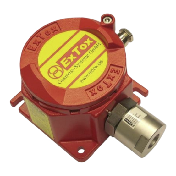
- Page 7 Instruction Manual ExTox Transmitter ExSens(-I) and Sens(-I) Housing Cable Glands im Grundgehäuse Sensor Element Sensor Cap Gas Inlet Sensor Page 7 of 20...
-
Page 8: Operation Of Transmitter
Instruction Manual ExTox Transmitter ExSens(-I) and Sens(-I) Operation of Transmitter Measuring Mode and Special Modes Normal operation for a transmitter means measuring mode during which the con- centrations of measured gas are monitored and transferred to the control unit. Fur- thermore the transmitter is able enter additional so-called special modes due to user operation or faults. -
Page 9: Start-Up Phase
Instruction Manual ExTox Transmitter ExSens(-I) and Sens(-I) Start-up Phase 3.2.4 When over-plugging the power supply at initial operation or after a power failure the transmitter has to stabilise itself. During this start-up phase invalid measuring signals could trigger false alarms. To avoid this, a constant current of 0.8 mA is is- sued during this start-up phase. -
Page 10: Change Of Sensor Element
You have to loosen the two grub screws which serve as protection against twisting first – for working on the ExSens(-I). Then you have to turn off the sensor element from the housing. To loosen the bolted connection use an open-ended wrench size 41 mm. -
Page 11: Operation Hints
Instruction Manual ExTox Transmitter ExSens(-I) and Sens(-I) Operation Hints Measuring Function The use of Gas Detection Systems for explosion and health protection requires spe- cial care. Besides qualified support of ExTox and the detailed information in the Transmitter Data Sheets ( DB) there are several guides to assist you for the safe use and operation of Gas Detection Systems. - Page 12 Zone 1 and 2. You will find all details regarding ignition protection and EC-Type Ex- amination Certificate BVS 04 ATEX 066 X on the ExSens Data Sheet ( DB). The limitation X refers to the types for measurement of flammable gases if these should perform a measuring function for the explosion protection in terms of regulation 2014/34/EU ("ATEX").
-
Page 13: Installation And Initial Operation
The connection of the transmitter is done via a double shielded line. For the ExSens and Sens it has to be a 3- or 4-wire line, for the ExSens-I and Sens-I it has to be a 5- or 6-wire line. The 6-wire and 4-wire line respectively are necessary in case the connection to ground cannot be done directly at place of installation of the trans- mitter. -
Page 14: Cable Gland And Shield
Sens(-I) the outer connection to ground has to be done at one fixing screws when installing. There is no marking. Connection of the ExSens-I and Sens-I is possible for line cross-sections up to 1 mm (cross-section 1.5 mm²). The outer connection of the ExSens-I is designed for line cross-sections up to 2 mm (cross-section 4 mm²). - Page 15 Instruction Manual ExTox Transmitter ExSens(-I) and Sens(-I) In case the transmitter behaviour does not correspond to that in normal measuring operation (Chapter 3.2.1), please make use of the hints in Chapter 3.3 for diagno- sis and removal of annoyances. Page 15 of 20...
-
Page 16: Maintenance
Instruction Manual ExTox Transmitter ExSens(-I) and Sens(-I) Maintenance The following descriptions are generally valid for Gas Detection Systems of the company ExTox GmbH consisting of the herein described control units and connect- ed transmitters. Basic Information Maintenance done by specialists is an indispensable measure for checking and keeping the functionality of gas detection systems. -
Page 17: System Check
Instruction Manual ExTox Transmitter ExSens(-I) and Sens(-I) of measured values at application of test gas is determined and compared with the nominal values. In case the settings are corrected additionally the process is called adjustment. In case of combination with sampling systems their correct function has also to be checked. -
Page 18: Performance Of Adjustment
Please pay also attention to the remarks for calibration in Chapter 6.5.1 when per- forming the adjustment. Adjustment for ExSens and Sens can also be done without RS 485-Communication as per description in Chapter 6.5.2.2. But the drift values evaluated by the Soft- ware ComSens will be invalid. - Page 19 Instruction Manual ExTox Transmitter ExSens(-I) and Sens(-I) The potentiometer to adjust the zero point is marked with "Zero", the one to adjust the sensitivity is marked with "Sens". All other potentiometer are adjusted and sealed factory-sided. It is not allowed to adjust them.
-
Page 20: Technical Data
Fixing Angle 90° for installation at the ceiling (Sens-I) 850002 Adapter for pipe installation (ExSens-I) 850003/07/08 Pipe Adapter Steel (ExSens WT,HL,IR / ExSens EC / ExSens KE) 850005 Pipe Adapter Stainless Steel (Sens) 850004/10/09 Pipe Adapter Stainless Steel (ExSens WT,HL,IR / ExSens EC /...
Need help?
Do you have a question about the ExSens and is the answer not in the manual?
Questions and answers