
Subscribe to Our Youtube Channel
Related Manuals for SMC Networks XSA Series


Summary of Contents for SMC Networks XSA Series
- Page 1 Doc. No. XSA-OMS0001-B PRODUCT NAME High Vacuum Solenoid Valve MODEL / Series / Product Number XSA Series...
-
Page 2: Table Of Contents
Contents Safety Instructions - - - - - - - - - - - - - - - - - - - - - - - - - - - - 1. Product Specific Precautions 1 - - - - - - - - - - - - - - - - - - - - - - - - - - - - (Precautions on Design, Selection, Mounting, Piping, Wiring, Maintenance) 2. -
Page 3: Safety Instructions
Safety Instructions These safety instructions are intended to prevent hazardous situations and/or equipment damage. These instructions indicate the level of potential hazard with the labels of “Caution,” “Warning” or “Danger.” They are all important notes for safety and must be followed in addition to International Standards (ISO/IEC) , and other safety regulations. - Page 4 Safety Instructions Caution We develop, design, and manufacture our products to be used for automatic control equipment, and provide them for peaceful use in manufacturing industries. Use in non-manufacturing industries is not covered. Products we manufacture and sell cannot be used for the purpose of transactions or certification specified in the Measurement Act.
-
Page 5: Product Specific Precautions 1
1. Product Specific Precautions 1 Precautions 1 Be sure to read before handling. Design Caution ⚫ Not suitable for use as an emergency shutoff valve, etc. The valves listed in this catalog are not designed for safety applications such as an emergency shutoff valve. - Page 6 Caution (5) Leakage voltage Switching element Particularly when using a resistor in parallel with a Leakage voltage switching element and using a C-R element (surge voltage suppressor) to protect the switching element, Power take note that leakage current will flow through the supply Leakage current resistor, C-R element, etc.,...
- Page 7 Wiring Caution (1) Use wiring cable with a cross section of 0.5 to 1.25mm . Make sure that no excessive force is applied to the wires. (2) Use electrical circuits which do not generate chattering within their contacts. (3) Use voltages which are within +/-10% of the rated voltage. If a direct current power supply is used and the response is important, the voltage should be within +/-5% of the rated value.
-
Page 8: Product Specific Precautions 2
2. Product Specific Precautions 2 Electrical wiring Caution ■ Grommet Class B coil: AWG20 Insulator O.D.2.5mm Lead wire color Rated voltage Black 100VAC Blue Blue 200VAC Other AC Grey Grey * There is no polarity. ■ DIN terminal Since internal connections are shown below for the DIN terminal, make connections to the power supply accordingly. - Page 9 ◼ Conduit terminal Wire the conduit terminal as illustrated below: ・ Tighten parts to the torque values specified below. ・ Seal the piping (G1/2) properly with the specified conduit. Terminal cover Round head combination screw M3 Tightening torque: 0.5 to 0.6 N·m +...
- Page 10 Electrical circuit CAUTION [DC Circuit] Grommet, terminal, conduit terminal, conduit Grommet, Flat terminal Varistor With surge voltage suppressor Without electrical option DIN terminal, conduit terminal Varistor Light With surge voltage suppressor and LED 【AC circuit】 *For AC, the standard product is equipped with surge voltage suppressor. DIN terminal, conduit terminal Grommet, terminal,...
-
Page 11: Specifications
3. Specifications 3-1. Valve specifications XSA2-43 Model XSA1-11,12 XSA1-21,22 XSA2-22 XSA2-32 XSA3-32,33 XSA3-43 Note Operation Normally close Fluid Air,Inert gas Orifice diameter mmø Max. working pressure MPa (G) Max. operating pressure MPa(G) Max. operating pressure difference MPa Note Differential pressure MPa (G) 0.25 0.05 0.15... -
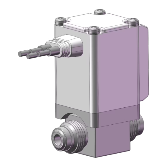
Page 12: Construction And Dimensions
4. Construction and Dimensions 4-1. Construction/Operation Components Description Material Solenoid coil Cu+Fe+Resin Core Tubing Seat (PET seat to shut the residual magnetism) Armature FKM, SUS, assembly Resin(PPS) Spring Body O-ring Port 1 Port 2 Spacer Poppet <Operation> When the solenoid coil(1) is energized, the suction force of the solenoid coil becomes larger than the accumulated force of the action force. - Page 13 4-2. Dimensions Grommet: G Face seal fitting / compression fitting Terminal part Flat terminal connector 250 Series - 12 - XSA-OMS0001-B...
- Page 14 Rc, NPT Ports Grommet G Fitting size 2 x M5 thread depth M Grommet: GS Flat terminal: F Conduit: C Terminal part Flat terminal connector 250 Series DIN terminal: D Terminal: T Applicable cable O.D.:ø6 to 12 Width across flats 22 - 13 - XSA-OMS0001-B...
-
Page 15: How To Order
5. How to order - 14 - XSA-OMS0001-B... -
Page 16: Special Option
6. Special Option Special Electrical Entry Direction - 15 - XSA-OMS0001-B... -
Page 17: Replacement Parts
7. Replacement Parts ●DIN Connector Part No. ●Gasket Part No. for DIN Connector VCW20-1-29-1(For Class B Coil) ●Lead Wire Assembly for Flat Terminal(Set of 2 pcs.) VX021S-1-16FB - 16 - XSA-OMS0001-B... -
Page 18: Period And Scope Of Warranty
8. Period and scope of warranty The warranty period is 2,000,000 cycles (under SMC endurance test conditions), 1 year in service or within 1.5 years after delivery, whichever comes first. If the valve has been used outside of the specifications, or if a failure occurs as a result of mounting onto a machine or reassembling by the user, the guarantee is void. -
Page 19: Troubleshooting
9. Troubleshooting This section summarizes troubleshooting the product. Refer to the table on the next page for troubleshooting measures. For disassembly and re-assembly, refer to the drawing below. If the problem is not resolved, please contact SMC. Mounting screws Disassembly (1)Before disassembling, shut off the power supply and air supply source to discharge the residual pressure. - Page 20 Troubleshooting Phenomenon Cause How to check Countermeasures Adherence of Check that there is no foreign foreign matter to matter stuck to the seal. Foreign matter has entered from outside and is stuck to the seal. the seal Take measures to prevent entrapment of foreign matter. Scratches on the Check that there are no Piping...
- Page 21 Revision history RENEWAL 2024.08 1st printing: 2014.05 Tel: + 81 3 5207 8249 Fax: +81 3 5298 5362 https://www.smcworld.com Note: Specifications are subject to change without prior notice and any obligation on the part of the manufacturer. © SMC Corporation All Rights Reserved - 20 - XSA-OMS0001-B...
Need help?
Do you have a question about the XSA Series and is the answer not in the manual?
Questions and answers