
Related Manuals for SMC Networks XLA-2 Series


Summary of Contents for SMC Networks XLA-2 Series
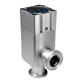
- Page 1 Doc. no.XL-OMS0001-D PRODUCT NAME High Vacuum L Type Valve MODEL / Series / Product Number XLA-2 Series...
-
Page 2: Table Of Contents
Contents Safety Instructions - - - - - - - - - - - - - - - - - - - - - - - - - - - - 1. Product Specific Precautions 1 - - - - - - - - - - - - - - - - - - - - - - - - - - - - (Piping, Air Supply) 2. -
Page 3: Safety Instructions
Safety Instructions These safety instructions are intended to prevent hazardous situations and/or equipment damage. These instructions indicate the level of potential hazard with the labels of “Caution,” “Warning” or “Danger.” They are all important notes for safety and must be followed in addition to International Standards (ISO/IEC) , and other safety regulations. - Page 4 Safety Instructions Caution We develop, design, and manufacture our products to be used for automatic control equipment, and provide them for peaceful use in manufacturing industries. Use in non-manufacturing industries is not covered. Products we manufacture and sell cannot be used for the purpose of transactions or certification specified in the Measurement Act.
-
Page 5: Product Specific Precautions 1
1. Product Specific Precautions 1 Precautions 1 Be sure to read before handling. Piping Caution 1. Refer to the Fittings and Tubing Precautions on the SMC website for handling One-touch fittings. 2. Before piping is connected, it should be thoroughly blown out with air (flushing) or washed to remove chips, cutting oil and other debris from inside the pipe. -
Page 6: Product Specific Precautions 2
2. Product Specific Precautions 2 Precautions 2 Be sure to read before handling. Design Warning ●All models 1. The body material is A6063, the bellows is SUS316L, and other metal seal material is SUS304. Refer to Chapter 5, “Construction and Dimensions” (P. 11) for details. Standard seal material in the vacuum section is FKM that can be changed to the other materials. - Page 7 ●High temperature type (temperature specification / H0 H4 H5) 1. In models with a heater (thermistor), take care not to damage the insulation components of the lead wires and connector section. 2. The set temperature for models with a heater should be established at normal ambient temperature without any drafts or heat insulation.
-
Page 8: Product Specific Precautions 3
3. Product Specific Precautions 3 Precautions 3 Be sure to read before handling Maintenance Parts Caution SMC specified parts should be used for maintenance service. Refer to Chapter 5, “Construction and Dimensions" (P. 11) for the part indication numbers. Bonnet assembly/Part indication number (1) Temperature Valve size Indicator... - Page 9 Bellows assembly, Nut assembly Valve size Description Part indication No. Bellows assembly XL1A16-2-101 XL1A25-2-101 XL1A40-2-101 XL1A50-2-101 Nut assembly XL1A16-10-1 XL1A25-10-1 XL1A40-10-1 XL1A50-10-1 Valve size Description Part indication No. Bellows assembly XL1A63-2-101 XL1A80-2-101 Nut assembly XL1A50-10-1 XL1A80-10-1 Note 1) Bellows assembly contains the valve seal 1. It does not contain the valve seal 2. Order separately if it is required.
-
Page 10: Specifications
4. Specifications 4-1. Valve specifications Model XLA-16-2 XLA-25-2 XLA-40-2 XLA-50-2 XLA-63-2 XLA-80-2 Flange (valve) size Actuating type Normally closed Fluid Vacuum of inert gas Operating temperature 5 to 60 (5 to 150 for high temperature type) Operating pressure Pa(abs) Atmospheric pressure to 1 x 10 Conductance l/s Note 1) 1.3 x 10... - Page 11 4-2. Heater specifications Item XLA-25-2 XLA-40-2 XLA-50-2 XLA-63-2 XLA-80-2 90 to 240 ACV Rated voltage of the heater Heater assembly number XL1A25-60S-1 XL1A25-60S-1 XL1A25-60S-2 XL1A25-60S-3 No. of heater assemblies 1 pc. 1 pc. 1 pc. 1 pc. Initial power / 100 VAC 200/40 200/50...
-
Page 12: Construction And Dimensions
5. Construction and Dimensions 5-1. Construction Auto switch (Optional) Bonnet assembly (Maintenance part) Indicator (Optional) (Including 2, 3, 7, 9, and 10) Magnet (Optional) Pilot port Cylinder Bellows holder (Material: SUS304) Heater (Optional) External seal (Maintenance part) Shaft (Material: SUS304) Bellows assembly (Maintenance part) (Including 6, 8) Bellows (Material: SUS316L) - Page 13 5-2. Dimensions G Unit: mm Model XLA-16-2 XLA-25-2 XLA-40-2 XLA-50-2 XLA-63-2 XLA-80-2 - 12 - XL-OMS0001-D...
-
Page 14: How To Order
6. How to order X L A A ( - X A N1 A ) Part with changed seal material Symbol Changed part Flange size Size None ②,③,④ ②,③ ④ ② ②,④ *See the Contruction and part page11 Flange type Seal material FKM(Standard) Applicable flange... -
Page 15: Period And Scope Of Warranty
7. Period and Scope of Warranty The warranty period is 2,000,000 cycles (under SMC's endurance test conditions), 1 year in service or within 1.5 years after delivery, whichever comes first. If the valve has been used outside of the specifications, or if a failure occurs as a result of mounting onto a machine or replacement of an assembly, seals, or etc. -
Page 16: Parts Replacement Procedure
8. Parts Replacement Procedure 8-1. Precautions Be sure to adhere to the instructions given in “2. Precautions 2“, when disassembling the product for maintenance. Along with the precautions listed in Chapter 2, the user should comply with those listed below. Warning •... - Page 17 8-2. Disassembly Procedure Step 1 Removal of bonnet assembly Step 2 Removal of valve seal 1 Valve Bolt Valve seal 1 Bottom surface of the Bonnet assembly groove to discharge gas. Pilot port Bonnet assembly Body Supply air pressure of 0.4MPa (G) to the pilot port. Remove the valve seal 1 from the seal mounting Loosen the bolts in numerical order to disassemble groove.
- Page 18 8-3. Assembly Procedure Step 1 Preparation Step 2 Reassembly of bellows assembly Apply a spanner to the Note) width across the flats of For XLA-16/25, mount the washer in the Clean cloth the shaft to prevent it orientation that the groove of the washer faces to the valve seal 2.
- Page 19 Step 5 Remount of external seal Step 6 Reassembly of bonnet assembly (No.1) Valve seal 1 External seal Mounting part of the external seal Bellows holder Bonnet assembly Body Wipe off any dust from the surface of the external Wipe off any dust from the surfaces of the valve seal and the mounting surface of the external seal seal 1 and the bellows holder.
- Page 20 8-4. Heater Replacement Procedure Step 1 Assembly of heater Heat transfer sheet Heater Heater Body Mounting screw Body Heater cover Mounting screw Heater cover Size 25 Size 40 or larger Put heat transfer sheet(Note1), heater, heater cover to backside of body. Tighten the mountiug screws to install heater assembly.
- Page 21 Revision D RENEWAL 2024.5 1st Printing: 2014.7 Tel: + 81 3 5207 8249 Fax: +81 3 5298 5362 https://www.smcworld.com Note: Specifications are subject to change without prior notice and any obligation on the part of the manufacturer. © SMC Corporation All Rights Reserved XL-OMS0001-D...
Need help?
Do you have a question about the XLA-2 Series and is the answer not in the manual?
Questions and answers