
Related Manuals for SMC Networks XLA Series


Summary of Contents for SMC Networks XLA Series
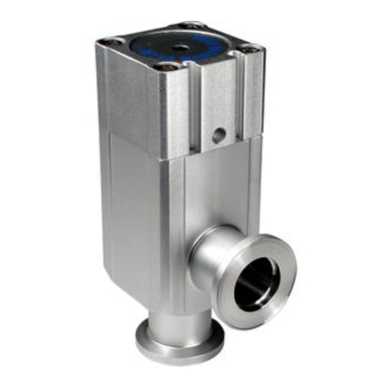
- Page 1 Doc. no.XL*****-OMI0009-E High Vacuum L Type Valve PRODUCT NAME XLA Series MODEL / Series / Product Number...
-
Page 2: Table Of Contents
Contents Safety Instructions - - - - - - - - - - - - - - - - - - - - - - - - - - - - 1. Product Specific Precautions 1 - - - - - - - - - - - - - - - - - - - - - - - - - - - - (Precautions on Design, Selection, Mounting, Piping, Wiring, Maintenance) 2. -
Page 3: Safety Instructions
Safety Instructions These safety instructions are intended to prevent hazardous situations and/or equipment damage. These instructions indicate the level of potential hazard with the labels of “Caution,” “Warning” or “Danger.” They are all important notes for safety and must be followed in addition to International Standards (ISO/IEC)*1), and other safety regulations. - Page 4 Safety Instructions Caution 1.The product is provided for use in manufacturing industries. The product herein described is basically provided for peaceful use in manufacturing industries. If considering using the product in other industries, consult SMC beforehand and exchange specifications or a contract if necessary. If anything is unclear, contact your nearest sales branch.
-
Page 5: Product Specific Precautions
1. Product Specific Precautions 1 Precautions 1 Be sure to read before handling. Design Warning ●All models 1. The body material is A6063, the bellows is SUS316L, and other metal seal material is SUS304. Standard seal material in the vacuum section is FKM that can be changed to the other materials (please refer “How to Order”). - Page 6 4. If the valve is to be insulated, only the body should be insulated, excluding the bonnet part. 5. In models with a heater, when the heater is in operation, the entire valve becomes hot. Be careful not to touch it with bare hands, as burns will result. 6.
-
Page 7: Product Specific Precautions
2. Product Specific Precautions 2 Precautions 2 Be sure to read before handling Maintenance Parts Caution SMC specified parts should be used for service. Refer to the construction drawing. 1.Replace the bonnet assembly when changing the seal material. Due to the different materials used, changing only the seal may prove inadequate. - Page 8 Additional symbols of the seal materials Barrel FKM for ULTIC Seal material EPDM Kalrez Chemraz ARMOR Perfluoro PLASMA Combination No. 2101-80 4079 SS592 SS630 SSE38 1232-70 3310-75 UA4640 Symbol -XN1 -XP1 -XQ1 -XR1 -XR2 -XR3 -XS1 -XT1 -XU1 Note1) Due to the different materials used, changing only the seal may prove inadequate. Barrel Perfluoro is a registered trademark of MATSUMURA OIL Co.,Ltd.
-
Page 9: Specifications
3. Specifications 3-1. Vale specifications Model XLA-16 XLA-25 XLA-40 XLA-50 XLA-63 XLA-80 XLA-100 XLA-160 Flange (valve) size Actuating type Normally closed Fluid Vacuum of inert gas Operating temperature 5 to 60 (5 to 150 for high temperature type) Operating pressure Pa(abs) Atmospheric pressure to 1 x 10 Conductance l/s Note 1... - Page 10 3-2. Heater specifications XL□-25 XL□-40 XL□-50 XL□-63 Item Rated voltage of the heater 90 to 240 ACV Heater assembly number XLA25-60S-1 XLA25-60S-1 XLA25-60S-2 No. of heater assemblies 1 pc. 1 pc. 1 pc. Initial power / 100 VAC 200/40 200/50 400/100 Power 200 VAC...
-
Page 11: Construction And Outer Dimensions
4. Construction and Outer dimensions Auto switch (option) Indicator (option) Bonnet assembly (maintenance part) Magnet (option) Pilot Port (opened by applying pressure) Bellows holder (material: SUS304) Heater (option) External seal (maintenance part) Bellows (material: SUS316L) Valve (material: SUS304) Valve seal (maintenance part) Body (material: A6063) Heater (option) Auto switch (option) -
Page 12: Period And Scope Of Warranty
5. Period and scope of warranty The guaranteed period covers the period which finishes the earliest among 2 million operating cycles (for size 16 to 80) or 1 million operating cycles (for size 100 and 160) [with our durability test conditions], 18 months after shipping from us, and 12 months after starting the use of the product at your place or your customer’s place. -
Page 13: Parts Replacement Procedure
6. Parts Replacement Procedure 6-1. Precautions Be sure to follow [1. Precautions 1] when disassembling the product for maintenance. Along with the precautions above, comply with the following precautions too. Warning • If it is expected that product materials may get stuck to the product, ensure safety is confirmed before handling. - Page 14 6-2. Disassembly procedure Step 1 Step 2 Bolt b O-ring Bottom surface of groove Bonnet assembly discharge gas. Heater Pilot port Bolt a Cover Body The heater is removed by loosening bolt a. Bolt Remove the O-ring from the groove for a is behind the cover.
- Page 15 6-3. Assembly Procedure Step 1 Step 2 O ring groove Valve Clean cloth Ethanol Assemble parts eliminating any dust or debris. Eliminate any dust within O-ring groove of the Wipe off dust with a clean cloth soaked with valve. ethanol. Blow parts with clean air if necessary. (Ensure there is no fibers or dust.
- Page 16 Step 5 O-ring Bellows holder Wipe off any dust from the valve seal O-ring and the Bellows holder surface. Step 6 Bolt b Tightening torque of bolt a Tightening torque of bolt b N・m N・m Tightening Valve size torque Valve Tightening size torque...
- Page 17 Revision E Precaution for mounting added. 2018.9 4-14-1, Sotokanda, Chiyoda-ku, Tokyo 101-0021 JAPAN Tel: + 81 3 5207 8249 Fax: +81 3 5298 5362 http://www.smcworld.com Note: Specifications are subject to change without prior notice and any obligation on the part of the manufacturer. ©...
Need help?
Do you have a question about the XLA Series and is the answer not in the manual?
Questions and answers