
Related Manuals for Johnson Controls SABROE UniSAB 4


Summary of Contents for Johnson Controls SABROE UniSAB 4
- Page 1 UniSAB 4 Safety, Installation, and Operating Guide Version 1.00 Safety, Installation, and Operating Guide IR-SAB-USR-0001-001-en 2024-06-21 New Release...
- Page 2 UniSAB 4 Safety, Installation, and Operating Guide...
-
Page 3: Table Of Contents
Contents Safety and installation............................. 5 Preface..............................5 Intended use............................6 Purpose of the manual..........................6 Equipment variants..........................6 Safety...............................6 Safety symbols..............................6 Safety precautions............................8 Equipment ratings............................8 Mounting instructions...........................9 Placement of the controller........................9 Mounting the cabinet version: not UL-certified..................9 Mounting the panel version: UL-certified....................11 Electrical installation..........................13 Installation materials.......................... - Page 4 Factory reset............................38 Resetting the controller..........................38 Connecting to the controller remotely....................38 User management..........................40 Logging on for the first time........................40 Logging on with a high security level...................... 40 Logging on with a low security level......................41 Accessing the controller in viewer mode....................41 Changing the password..........................
-
Page 5: Safety And Installation
Phone +45 8736 7000 www.sabroe.com This manual must not be copied without the written permission of Johnson Controls Denmark, and the contents must not be imparted to any third parties nor be used for any unauthorized purposes. Contravention will be prosecuted. -
Page 6: Intended Use
Intended use The UniSAB 4 controller is for reciprocating and screw compressors applications and is intended for: • Monitoring • Protection • Controlling • Regulating Depending on configuration, the UniSAB 4 controller can be used in standalone applications or form part of a larger cooling or heating application system. The UniSAB 4 controller is intended for use in industrial and commercial environments in accordance with local laws and standards. - Page 7 Indicates that the marked item can be hot and should not be touched without taking proper precautions UniSAB 4 Safety, Installation, and Operating Guide...
-
Page 8: Safety Precautions
Safety precautions Missing connectors Missing connectors can result in direct access to hazard electrical supply pins. Hot surface Environmental conditions can result in hazard hot surface of the metal cover. Equipment ratings For the electrical and environmental ratings, see the following tables: Table 1: Electrical conditions Rated voltage 100 VAC to 240 VAC... -
Page 9: Mounting Instructions
Mounting instructions The UniSAB 4 controller is available in two versions: • Cabinet version, used as a standalone controller that mounts on to the unit frame. Panel version, which mounts in an electrical panel. • Placement of the controller Choose a location that has free space in front of, and on both sides of the UniSAB 4 controller, to operate in a freely and safe manner. - Page 10 Figure 3: UniSAB 4 cover Callout Component Screws Note: The front cover is connected to the enclosure with cables and cannot be fully detached from the enclosure. The front cover screws are equipped with retainer quick lock to prohibit the screws from falling out.
-
Page 11: Mounting The Panel Version: Ul-Certified
Mounting the panel version: UL-certified The panel version controller is mounted as part of an electrical panel. Figure 4: Panel version Callout Component Callout Component I/O board Touchscreen display I/O board mounting plate LAN cable Use the pre-drilled holes and four screws to install the I/O board mounting plate on to the backplate of the electrical panel. - Page 12 Figure 5: Screw locations for mounting to the electrical panel door Callout Component Screws UniSAB 4 Safety, Installation, and Operating Guide...
-
Page 13: Electrical Installation
Electrical installation Installing the UniSAB 4 includes electrical installation, and must comply with the following points: • Installation, start-up, and maintenance must only be performed by qualified personnel • Ensure that electrical work conforms to national and local electrical codes •... - Page 14 Figure 6: Cable routing Callout Description Cable route for > 24 V cables Cable route for < 24 V cables Figure 7: Cable ties Flanges and cable glands To maintain the UL certification, install the listed flanges and cable glands or blind plugs. See Table 4.
- Page 15 Figure 8: Flanges and cable glands Table 4: Gland type information Callout Manufacturer Model Image Quantity Cable range Ø mm Murrplastik KDP/N 2417 5.00 – 9.20 4 – 1/0 Murrplastik KDP/N 2414 3.00 – 6.50 8 – 2 5.00 – 9.20 4 –...
-
Page 16: Power Supply And Protective Earthing
Panel cable installation Electrical panels are subject to national and local electrical codes and regulations. Cable management must comply with these codes and regulations. Figure 9: Panel version Callout Description I/O board Touch screen: back side Mounting plate Power supply and protective earthing Supplying power to the cabinet version Connect the Line (L) and Neutral (N) of the power supply (1) directly to the L and N terminal pin of X20 terminal, on the I/O board. - Page 17 Figure 10: Cabinet power connections Callout Description Callout Description UniSAB power supply cable Earth connector PE connection wire to the I/O board PE must be minimum 2x length of Minimum wire cross-section: 2.5 (L) and (N) conductor /AWG 14. Figure 11: Example of binding screw assembly (3) Supplying power to the panel version Connect the Line (L) and Neutral (N) of the power supply (1) directly to the L and N terminal pin of X20 terminal, on the I/O board.
- Page 18 Figure 12: Panel power connections Callout Description Callout Description UniSAB power supply cable Earth connector PE connection wire to the I/O board PE must be minimum 2x length of Minimum wire cross-section: 2.5 (L) and (N) conductor /AWG 14. Figure 13: Example of binding screw assembly (3) Connect the earthing point of the touchscreen to an earthing terminal with a yellow and green PE wire.
-
Page 19: Input And Output I/O Overview
Figure 14: Earthing point Note: Minimum wire cross-section: 2.5 mm /AWG 14 Input and output I/O overview This section gives an overview of the I/O board inputs and outputs, the controller, and their general usage and ratings. I/O board Figure 15: I/O board UniSAB 4 Safety, Installation, and Operating Guide... -
Page 20: Controller
The I/O board has a total of 18 plug connectors. It can be extended with a Profibus DP communication board. See Table 5 for I/O connectors description and conductor criteria. For more information on the usage of individual I/O ports and pins, refer to the UniSAB 4 Engineering manual. - Page 21 Figure 16: Controller port overview Table 6: Controller port overview Connector name Description Function Power: 24 VDC Not used RS485 Not used Status indicator Pre-mounted Display LAN RJ45 port HDMI Not used Micro USB Micro USB USB-A USB-A SD-card slot Not used UniSAB 4 Safety, Installation, and Operating Guide...
-
Page 22: Power Supply
Power supply Ensure the UniSAB 4 controller power supply includes a circuit breaker, which complies with the following points: • Ensure the circuit breaker is suitably located and easily reached. If not, install a service switch that is suitably located and easily reached. •... - Page 23 Figure 18: Power supply installation Circuit breaker and service switch Table 7: Power supply overview Callout Component Requirements Voltage Current Permitted rating rating characteristics Circuit Clearly marked as the 100 VAC to Max. 10 A* Type C-curve breaker primary disconnecting 240 VAC device for the specific Fuse...
-
Page 24: Operating Safety: Emergency Stop
If it is necessary to service the UniSAB 4 control system, the power supply to the compressor motor must be switched off on the main switch to prevent the compressor from starting up accidentally. As the UniSAB 4 box contains live parts, it is very important to comply with the safety regulations on site. - Page 25 Ensure that all connectors are attached to the terminals at all times when the UniSAB 4 controller is powered on. Missing connectors can result in direct access to hazard electrical supply pins. The metal on the backside of the front can be hot! Loosen the two screws in the front of the cabinet.
-
Page 26: Spare Parts
Spare parts Only replace parts with the original spare parts. See Preface for contact information when ordering spare parts. Table 8: Spare parts Item Part number Profibus DP communication module 1571.1158 Cabinet front with Controller module 1573.1016 Panel front with Controller module 1573.1017 I/O module 1571.1172... -
Page 27: Safety Equipment
Safety equipment All safety circuit components are connected through the UniSAB 4 controller. The controller is a hardwired connection point for the components. No control logic is implemented into the safety circuit. The UniSAB 4 controller is not considered part of the safety circuit. Port X4 pin 7 and 8 activates an input signal to the UniSAB Controller for indication of an emergency stop. -
Page 28: Operation
Operation The purpose of the UniSAB 4 control system is to monitor, protect, control, and regulate reciprocating and screw compressors. The control cabinet and the electrical components are connected at the factory. As a result, there are only a few electrical installation connections needed on site. The UniSAB 4 is programmed according to the type of compressor it is going to control. -
Page 29: Main Interface Icons
Main interface icons Table 10: Main interface icons Icon Icon name Icon Icon name Home Alarm log Main menu Start Stop Capacity up Capacity down Manual mode Manual mode active – – To access the main menu, tap the Main menu icon. From the main menu, the user can access the following sub-menus: •... -
Page 30: Home Screen
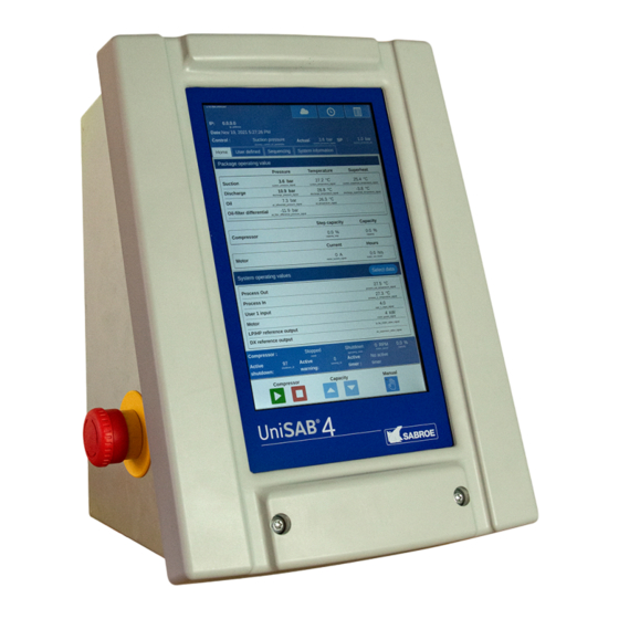
Home screen From the home screen, the operator can perform the following functions: Figure 21: Home screen Callout Description Switch between the home screen, alarm log, or main menu. Switch to sub-menus by tapping the following tabs: • Home • Operation values •... -
Page 31: Alarm Log
Alarm log To access the alarm log, tap the Alarm log icon. Figure 22: Alarm log icon location The alarm log can be in one of the following statuses: • Non-active warnings or shutdowns • Active shutdowns • Active warnings Figure 23: Alarm log Note: Tapping Reset acknowledges the alarms. -
Page 32: Handling An Active Warning
Table 11: Alarm icons Alarm icon Description Historical Active warning Active shutdown Tap on the info icon to get information about the input and output signal values from the alarm. For more information, refer to the UniSAB 4 Engineering Guide. Handling an active warning Tap Reset to reset, or disconnect, the warning relay. -
Page 33: Control State
Control state The UniSAB 4 logo at the bottom of the controller lights up differently depending on the controller state. See the following table for controller state and the corresponding lighting. Table 12: UniSAB 4 logo lighting State Light of UniSAB 4 logo Stopped None Ready... -
Page 34: Changing Values
Changing values In general, changeable fields can either be changed from a dropdown list or an input field. Changeable fields have a yellow background. Fields with a dropdown list can be changed by tap the field and choose a value from the dropdown list. -
Page 35: Changing Alphanumeric Values
Changing alphanumeric values Figure 26: Alphanumeric keyboard Tap the field value you want to change. In the input field, change the value by using the keyboard. • Tap ← to delete from right to left. • Tap ↑ to switch caps on or off. •... -
Page 36: Control Mode
Control mode The compressor can be set up for different modes of operation. As a result, the UniSAB 4 controller has the following modes: Stopped: The compressor is blocked and cannot start. • • Manual: The compressor is operated manually. Use the following icons to control the compressor: Start Stop... -
Page 37: Language Options
Language options You can change the UniSAB 4 controller interface text to any of the following languages: • English: default • German • Greek • Arabic • Danish • French • Spanish • Italian • Polish • Dutch • Finnish •... - Page 38 Factory reset On delivery the UniSAB 4 is preset with factory settings for all appropriate points. If any values were added, removed, or changed from the factory settings, you can reset the UniSAB 4 to these settings. There are two levels of factory reset: reset settings and factory reset. Reset settings is a partial reset and only resets the following configurations: •...
- Page 39 Figure 28: Loading screen Note: If the UniSAB 4 controller loading screen does not appear, contact the network administrator to verify you are authorized to access the UniSAB 4 Controller from your device. UniSAB 4 Safety, Installation, and Operating Guide...
- Page 40 User management The UniSAB 4 controller has two levels of user security: • Low security: In this security level, there are three predefined users: user, superuser and supervisor. Each has different permissions to make changes. Only the administrator has permissions to update the passwords for the three users. High security: In this security level, the administrator creates individual users with different •...
- Page 41 Logging on with a low security level Tap the Main menu icon in the upper-right corner and select Login. From the User Level list, select the appropriate user level. In the Password field, enter the correct password. Tap Login. Accessing the controller in viewer mode You can access the controller in viewer mode without a password.
- Page 42 © Johnson Controls. All rights reserved. Subject to change without notice. Johnson Controls Denmark ApS. SABROE Factory. Christian X's Vej 201 8270 Højbjerg Denmark. Phone +45 87 36 70 00. www.sabroe.com...
Need help?
Do you have a question about the SABROE UniSAB 4 and is the answer not in the manual?
Questions and answers