Table of Contents
Advertisement
Application
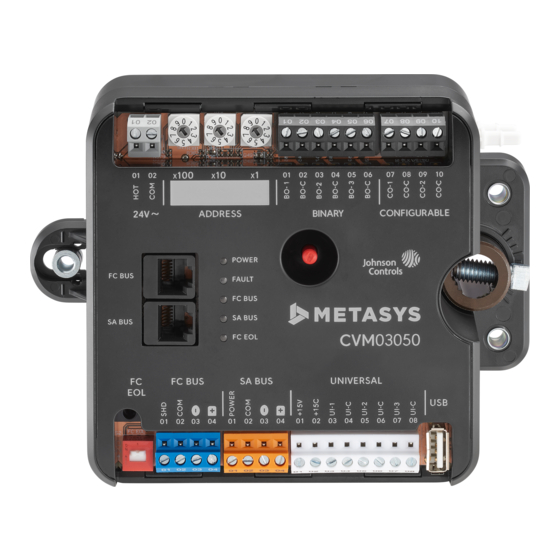
The CVM03050 equipment controllers are designed
for variable air volume (VAV) box applications.
CVM03050 controllers operate on an RS-485
BACnet
MS/TP bus as BACnet Advanced
®
Application Controllers (B-AACs) and integrate into
Johnson Controls
and third-party BACnet systems.
®
CVM03050 controllers feature an integral damper
actuator, a digital Differential Pressure Transmitter
(DPT) sensor, and a 32-bit microprocessor. These
controllers also include an integral real-time clock,
which enables the controllers to monitor and control
schedules, calendars, and trends, and operate for
extended periods of time as stand-alone controllers
when offline from the Metasys
These controllers connect easily to the wired and
wireless network sensors for zone and discharge
air temperature sensing. Their small package size
facilitates quick field installation and efficient use of
space without compromising control performance.
Communications protocols
The CVM03050 controllers can communicate using
BACnet MS/TP, N2, or wireless Zigbee
the CVM controllers communicate using the BACnet
MS/TP protocol. The BACnet protocol is a standard
for ANSI, ASHRAE, and the International Standards
Organization (ISO) for building controls.
The CVM controllers can be used as functional
replacements for legacy N2 controllers. The N2-
capable MS/TP equipment controller models
provide a cost-effective upgrade and modernization
path for customers with existing N2 controllers.
For installation and commissioning support,
and tips for efficient and safe replacement,
refer to the Modernization Guide for Legacy N2
Controllers (LIT-12012005) and the controller-
specific documentation. For information about
mapping N2 Objects in controllers with switchable
communications protocols, refer to the N2
Compatibility Options chapter of the Controller Tool
Help (LIT-12011147).
To configure CVM controllers to communicate using
the N2 communications protocol, see
N2
communications.
The CVM controller can also be installed in a
wireless application using a ZFR/ZFR ProWireless
M4-CVM03050 VAV Controllers Installation
system network.
®
. By default,
®
Configuring
Field Bus Router. To configure these controllers to
communicate using the wireless communications
protocol, see
Configuring wireless
North American Emissions
Compliance
United States
This equipment has been tested and found to
comply with the limits for a Class A digital device
pursuant to Part 15 of the FCC Rules. These limits
are designed to provide reasonable protection
against harmful interference when this equipment
is operated in a commercial environment. This
equipment generates, uses, and can radiate radio
frequency energy and, if not installed and used in
accordance with the instruction manual, may cause
harmful interference to radio communications.
Operation of this equipment in a residential area
may cause harmful interference, in which case the
users will be required to correct the interference at
their own expense.
Canada
This Class (A) digital apparatus meets all the
requirements of the Canadian Interference-
Causing Equipment Regulations.
Cet appareil numérique de la Classe (A) respecte
toutes les exigences du Règlement sur le matériel
brouilleur du Canada.
Installation
Observe the following guidelines when installing a
CVM controller:
• To minimize vibration and shock damage to the
controller, transport the controller in the original
container.
• Verify that all parts shipped with the controller.
• Do not drop the controller or subject it to physical
shock.
*241014301590B*
Guide
Part No. 24-10143-01590 Rev. B
2019-10-18
communications.
(barcode for factory use only)
M4-CVM03050
Advertisement
Table of Contents

Subscribe to Our Youtube Channel
Related Manuals for Johnson Controls M4-CVM03050


Summary of Contents for Johnson Controls M4-CVM03050
- Page 1 M4-CVM03050 VAV Controllers Installation Guide Part No. 24-10143-01590 Rev. B 2019-10-18 Application Field Bus Router. To configure these controllers to communicate using the wireless communications protocol, see Configuring wireless communications. The CVM03050 equipment controllers are designed for variable air volume (VAV) box applications.
-
Page 2: Parts Included
Supply power terminal block) terminals; can be defined as Voltage Analog Output (0– Device Address Rotary Switches (see Setting the device 10 VDC) or Binary Output (24 VAC Triac) (see Table 5) address) Dual Port Fitting M4-CVM03050 VAV Controllers Installation Guide... - Page 3 RTD: 1k Nickel, 1k Platinum, or A99B SI condensation to fall away from the controller. Additional measures may be required in some NTC: 10K Type L (10K Johnson Controls Type II is equivalent to Type L) or 2.252K Type II installations.
- Page 4 DP tubes to either barbed fitting on the CVM controller. You do not need to make a specific high- or low-side connection when you attach the tubing to the barbed fittings on the CVM. M4-CVM03050 VAV Controllers Installation Guide...
-
Page 5: Terminal Blocks And Bus Ports
électrique afin d'éviter tout risque de block plugs on the CVM and other controllers in a décharge électrique. daisy-chain configuration. For more information about FC Bus terminal functions, requirements, and ratings, see Table 7. M4-CVM03050 VAV Controllers Installation Guide... -
Page 6: Sa Bus Terminal Block
Balancing Tool, DIS1710 Local Controller Display, WRZ78xx Series One-to-One Wireless Transmitter, and NS Series sensors. Note: The MAP Gateway serves as a replacement for the BTCVT, which is no longer available for purchase, but continues to be supported. M4-CVM03050 VAV Controllers Installation Guide... -
Page 7: Supply Power Terminal Block
Table 4: Supply power terminal block wiring Description Supply power terminal block Supply power terminal header Wires from Johnson Controls 24 VAC, class 2 power transformer 24 VAC (Orange wire) M4-CVM03050 VAV Controllers Installation Guide... -
Page 8: Terminal Wiring Guidelines, Functions, Ratings, And Requirements
Input and Output wiring guidelines Table 5 provides information and guidelines about the functions, ratings, and requirements for the controller input and output terminals, and Table 5 also references guidelines for determining proper wire sizes and cable lengths. M4-CVM03050 VAV Controllers Installation Guide... -
Page 9: I/O Terminal Blocks, Ratings And Requirements
(Inputs) 1k Platinum, and A99B Silicon Temperature Sensor) Negative Temperature Coefficient (NTC) Sensor 10K Type L (10K Johnson Controls Type II is equivalent to Type L) or 2.252K Type II Binary Input - Dry Contact Maintained Mode 1 second minimum pulse width See Guideline A in Table 6. -
Page 10: Cable And Wire Length Guidelines
61 m (200 ft) twisted wire point. 107 m (350 ft) twisted wire See Figure 9 to select wire size/ See Figure 9 to determine cable gauge. length. Use stranded copper wire. Use twisted wire cable. M4-CVM03050 VAV Controllers Installation Guide... - Page 11 Function, electrical ratings/ Terminal block/Port label Terminal labels Recommended cable type Requirements FC Bus Communications 0.6 mm (22 AWG) stranded, 3-wire FC BUS Signal Reference (Common) for bus twisted, shielded cable recommended communications SHLD Isolated terminal M4-CVM03050 VAV Controllers Installation Guide...
- Page 12 The FC bus and SA bus wiring recommendations in this table are for MS/TP Bus communications at 38.4k baud. The MAP Gateway serves as a replacement for the BTCVT, which is no longer available for purchase, but continues to be supported. M4-CVM03050 VAV Controllers Installation Guide...
-
Page 13: Termination Diagrams
Termination diagrams A set of Johnson Controls termination diagrams provides details for wiring inputs and outputs to the controllers. See the figures in this section for the applicable termination diagrams. Table 8: Termination details Type of Input/ Type of Field Device... - Page 14 Low, External Source) Note: Applies to CO4 and CO5. Analog Output (Voltage) Incremental Control to Actuator (Switch Low, Internally Sourced) Note: Applies to BO3 (for only), BO1, and BO2. 24 VAC Binary Output (Switch Low, Internally Sourced) M4-CVM03050 VAV Controllers Installation Guide...
-
Page 15: Setup And Adjustments
N2 device addresses provided by the N2 firmware and controller application file protocol standard (1-254). configured for N2 to the controller. To configure a controller to communicate using the N2 protocol, complete the following steps: M4-CVM03050 VAV Controllers Installation Guide... -
Page 16: Configuring Wireless Communications
For details about setting a device address, see Setting the device address. Reconnect the 24 VAC supply to the controller. For more information about the ZFR Pro Wireless Field Bus system, refer to the WNC1800/ZFR182x M4-CVM03050 VAV Controllers Installation Guide... -
Page 17: Removing A Terminal Block
FC Bus, set the EOL switch to ON. If the screwdriver. controller is not a terminating device on the bus, set the EOL switch to OFF. M4-CVM03050 VAV Controllers Installation Guide... - Page 18 To commission the CVM03050 controller, use the following procedure: 1. Download the control application to the CVM controller using the CCT. Refer to the Controller Tool Help (LIT-12011147). 2. Commission the VAV Box. Refer to the Controller Tool Help (LIT-12011147). M4-CVM03050 VAV Controllers Installation Guide...
-
Page 19: Led Status And States
Off Steady = No data transmission (N/A - auto baud not supported) On Steady = Communication lost; waiting to join communication ring On Steady = EOL is active Amber Off Steady = EOL is not active M4-CVM03050 VAV Controllers Installation Guide... -
Page 20: General Troubleshooting
The Common Reference is incorrect. connected end device. Repair information For a replacement unit, contact the nearest Johnson Controls representative. If the CVM03050 equipment controller fails to operate within its specifications, replace the unit. M4-CVM03050 VAV Controllers Installation Guide... -
Page 21: Ordering Information And Accessories
(Y65SP+), 20.32 cm (8 in.), Primary Leads and Secondary Screw Terminals, Class 2 Replacement Barbed Fitting for Connecting Tubing, Bulk Pack of 10. For use on F-1000-325 CVM03050-0, and also on VMA1630, VMA1615, and VMA1832 Series models. M4-CVM03050 VAV Controllers Installation Guide... - Page 22 The FIT can be used to check out the wiring of the MS/TP RS-485 bus as well as verify proper communications of supervisory controllers and equipment controllers connected to the bus. The FIT can be used on both the FC Bus and SA Bus. TL-BRTRP-0 Portable BACnet/IP to MS/TP Router M4-CVM03050 VAV Controllers Installation Guide...
-
Page 23: Technical Specifications
165 mm x 125 mm x 73 mm (6.5 in. x 4.92 in. x 2.9 in.) (Height x Width x Depth) Center of Output Hub to Center of Captive Spacer: 135 mm (5-5/16 in.) Weight 0.69 kg (1.52 lb) M4-CVM03050 VAV Controllers Installation Guide... -
Page 24: Product Warranty
MILWAUKEE WI 53202 NO. 32 CHANGJIJANG RD NEW GERMANY DISTRICT WUXI JIANGSU PROVINCE 214028 CHINA © 2019 Johnson Controls. All rights reserved. All specifications and other information shown were current as of document revision and are subject to change without notice. www.johnsoncontrols.com...
Need help?
Do you have a question about the M4-CVM03050 and is the answer not in the manual?
Questions and answers