Table of Contents
Advertisement
Application
The Metasys
Network Control Engine (NCE) 25 Series controllers combine the network supervisor
®
capabilities and Internet IP network connectivity of a Metasys Network Automation Engine (NAE)
with the I/O point connectivity and direct digital control capabilities of a Metasys Field Equipment
Controller (FEC). These network engines provide a cost-effective solution designed for central plant
applications and large built-up air handlers.
NCE25 Series controllers provide integration to the following network protocols: BACnet/IP, BACnet
MS/TP, and N2 Bus and integrations to other building management communication technologies,
including Modbus
, M-Bus, and KNX. The network engine at 9.0.7 is shipped with the licenses and
®
drivers for all three communication protocols: Modbus, M-Bus, and KNX.
Note: LonWorks
®
LonWorks integration remain at Release 9.0 or earlier.
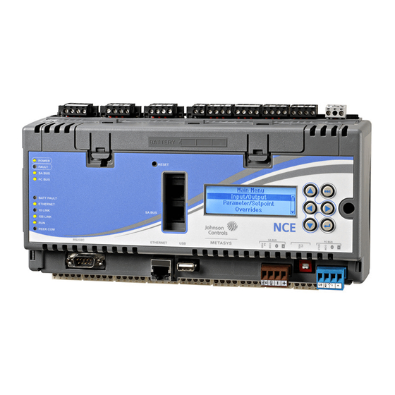
Figure 3 shows the physical features of an MS-NCE2567-0 model. See Table 18 for NCE25 Series
model information and features.
Important: For existing custom integrations, contact your local Systems Integration Services
(SIS) team before an upgrade. Updated drivers can be provided on request.
Installation
Follow these guidelines when installing an NCE:
• Transport the NCE in the original container to minimize vibration and shock damage to the
network .
• Verify that all the parts shipped with the NCE.
• Do not drop the NCE or subject it to physical shock.
Parts included
• One NCE with removable terminal plugs.
• One data protection battery installed and connected when the NCE is shipped.
• One installation instructions sheet.
Materials and special tools needed
• Three fasteners appropriate for the mounting surface (M4 screws [#8] screws).
• One 20 cm (8 in.) or longer piece of 35 mm DIN rail, and appropriate hardware for mounting the
DIN rail.
Mounting
Location considerations
Follow these guidelines when mounting a network engine:
• Ensure that the mounting surface can support the NCE and any user-supplied panel or enclosure.
Part No. 24-10143-63 Rev. S
2018-12-17
Release 9.0.7
is no longer supported for an NCE at Release 9.0.7. All NCEs that feature the
NCE25 Installation Instructions
*241014363S*
(barcode for factory use only)
Advertisement
Table of Contents

Related Manuals for Johnson Controls Metasys NCE25 series


Summary of Contents for Johnson Controls Metasys NCE25 series
- Page 1 NCE25 Installation Instructions Application The Metasys Network Control Engine (NCE) 25 Series controllers combine the network supervisor ® capabilities and Internet IP network connectivity of a Metasys Network Automation Engine (NAE) with the I/O point connectivity and direct digital control capabilities of a Metasys Field Equipment Controller (FEC).
-
Page 2: Wall Mount Applications
• Mount the NCE in a horizontal, upright orientation. • Mount the NCE on an even surface in wall mount applications whenever possible. If you must mount the network engine on an uneven surface, be careful not to crack the mounting clips or network engine housing when tightening the screws. -
Page 3: Din Rail Mount Applications
Figure 1: NCE mounting screw hole dimensions, (mm/in.), and mounting area requirements 4. Position the network engine and insert the screws through the holes in the mounting clips, and carefully tighten all the screws. Important: Do not overtighten the mounting screws. Overtightening the screws may damage the mounting clips or NCE housing. - Page 4 Figure 2: DIN rail and mounting clip features on the back of an NCE 3. Hang the network engine by the DIN rail hooks on the top track of the DIN rail, and position the network engine DIN rail channel snugly against the tracks of the DIN rail. See Figure 2. 4.
- Page 5 NCE25 physical features Figure 3: Front of NCE2567-0 showing physical features (power and I/O terminal blocks, and NCE mounting clips not shown) Table 1: Callout table for NCE25 physical features Callout Description The LED status indicators vary depending on the NCE model. See LED status indicators.
-
Page 6: Power Supply, Network, And Communication Connections
Table 1: Callout table for NCE25 physical features Callout Description FC Bus teminal block connects an NCE to an N2 Bus or FC Bus segment. It is not available on all models. End-of-Line (EOL) Termination Switch sets the NCE as an EOL terminating device. Set the EOL switch according to the NCE position on the N2 or FC Bus segment. - Page 7 • A Wireless Commissioning Converter (MS-BTCVT-1) to commission the network engine with the Controller Commissioning Tool. • A DIS1710 Local Controller Display to provide a display screen on NCE25 models without an integral display screen. • An NS Series Network Sensor to provide room temperature data to the network engine. Figure 4: Pin number assignments for Sensor, SA Bus, and FC Bus Ports on NCE, FEC, IOM, and VMA16 FC Bus terminal block...
-
Page 8: Wiring Rules For Networks And Field Buses
Standard USB port A network engine updated to Release 9.0.7, does not support modem functionality through the USB port. However, for a network engine with vendor integrations, you can configure the vendor integration to use an external flash drive connected to the USB port to capture diagnostic information when the engine is in diagnostic mode. -
Page 9: Sa Bus Rules
Table 3: FC Bus rules Category Rules/maximums allowed General One FC Bus with up to 32 MS/TP devices (on NCE256x models only). Note: An FC port on a network engine can connect to only one bus segment on an FC Bus. Only a daisy-chain topology is allowed (no T or Star topology configurations). -
Page 10: N2 Bus Rules
Table 4: SA Bus rules Category Rules/limits Cable length for SA Bus 365 m (1,198 ft) maximum bus length. 152 m (500 ft) maximum between an NS network sensor and the bus supervisor FEC or VMA supplying power to the sensor) using bus cable connected to the SA Bus screw terminal blocks. -
Page 11: Modbus Rtu Rules
Modbus RTU rules The RS-232 port supports the connection of one Modbus RTU (RS-232) device. With the addition of an RS-232/RS-485 converter and connection to the RS-232 port, up to 32 Modbus RTU (RS-485) devices are supported. Observe the rules in the following table when designing and installing the connected Modbus RTU Bus. -
Page 12: M-Bus Protocol Rules
M-Bus protocol rules Note: Unit load is a defined standby current. A device is permitted a current drain of one unit load by default but may consume more if it is shown at the device (by an integer) and in documentation. -
Page 13: Knx Protocol Rules
Table 7: Rules for M-Bus protocol Category Rules/maximums allowed 350 m (1,148 ft) 1,000 m (3,281 ft) (2 x 0.8 mm (20 AWG), shielded, resistance < 30 Ohms) 38,400 350 m (1,148 ft) 1,000 m (3,281 ft) (2 x 0.8 mm (20 AWG), shielded, resistance <... -
Page 14: Wiring For N2, Ms/Tp, Or Modbus Rtu Protocol
Table 9: Dual trunk options Trunk type Supported dual trunk application Modbus and M-Bus 1 RS232 Modbus 1 TCP M-Bus 1 RS232 M-Bus 1 TCP Modbus 1 TCP Modbus 1 TCP M-Bus Wiring Important: Do not connect 24 VAC supply power to the NCE before finishing wiring and checking all wiring connections. - Page 15 RS-485 bus is a two-wire network. See Figure 5. a. Connect the converter's + A terminal to the device's + (or A) terminal. b. Connect the converter's - B terminal to the device's - (or B) terminal. c. If the device has a Signal Ground or Reference terminal, connect this to the converter's CG2 terminal.
-
Page 16: Wiring For Serial M-Bus Protocol
Figure 8: 24 VAC Supply Power Wiring Note: Power supply wire colors may be different on transformers not manufactured by Johnson Controls. Follow the transformer manufacturer’s instructions and the project installation drawings. 7. Connect the 24 VAC supply power wires from the transformer to the converter. No additional external power adapter is required. -
Page 17: Wiring For Knx Protocol
4. Connect the 24 VAC supply power wires from the transformer to the removable power terminal block plug. Note: Power supply wire colors may be different on transformers not manufactured by Johnson Controls . Follow the transformer manufacturer’s instructions and the project ®... -
Page 18: Wiring Input And Output Terminals
Figure 10: KNX/IP Interface Router 3. For a single KNX line, wire from the red and black terminals on the gateway to the devices. For multiple KNX lines, wire from the red and black terminals on each gateway to the devices on the same KNX line. - Page 19 Figure 11: NCE25 series output terminal blocks, Binary output jumpers, and supply power terminal block as viewed from the top of an NCE25 Table 10: Call-out table for NCE25 series output terminal blocks, binary output jumpers, and supply power terminal block as viewed from the top of an NCE25 Callout Description Binary output - Two jumpers positioned for an internal source of power.
-
Page 20: Terminal Functions, Ratings, Requirements, And Wiring Guidelines
Table 11: Call-out table for Universal input and Binary input terminal blocks as viewed from the bottom of an NCE25 Callout Description Universal inputs can be defined as the following: • Voltage Analog inputs (0 -10 VDC) • Current Analog inputs (4-20 mA) •... -
Page 21: Terminal Wiring And Cable Length Guidelines
See Guideline A in Table (0–600k Ohms) Internal 12 V, 15k Ohms pull up. Qualified Sensors: 0–2k potentiometer, RTD (1k Nickel [Johnson Controls sensor], 1k Platinum, and A99B Silicon Temperature Sensor) NTC Sensor (10k Type L, 10k JCI Type II, 2.252k Type II). - Page 22 Table 12: Terminal wiring Terminal block Terminal labels Function, ratings, and Determine wire size label requirements and maximum cable length Binary Input - Pulse Counter Mode 0.01 second min. pulse width. (50 Hz at 50% duty cycle). Internal 18 V, 3k Ohms pull up. ICOMn Binary Input Common for all Binary Input (IN) terminals...
- Page 23 Table 12: Terminal wiring Terminal block Terminal labels Function, ratings, and Determine wire size label requirements and maximum cable length Analog Output - Current See Guideline B in Table Mode (4–20 mA) Requires an external load between 0–300 Ohms. Note: The AO operates in Current Mode when connected to devices with impedances less than 300...
- Page 24 Table 12: Terminal wiring Terminal block Terminal labels Function, ratings, and Determine wire size label requirements and maximum cable length BINARY OUTn Binary Output - 24 VAC Triac See Guideline C in Table (Internal Power) (Outputs) Sources internal 24 VAC power Power Selection (24~ HOT).
- Page 25 Table 12: Terminal wiring Terminal block Terminal labels Function, ratings, and Determine wire size label requirements and maximum cable length OCOMn Analog Output Signal Same as (Configurable) Common: All Configurable OUTn. Outputs defined as Analog Outputs share a common, which is isolated from all other commons except the Binary Input common.
-
Page 26: Maximum Cable Length Versus Load Current
Table 13: Cable length guidelines for recommended wire sizes Guideline Wire size/gauge and type Maximum cable Assumptions length and type See Figure 13 to select wire size/ See Figure 13 to gauge. Use stranded copper wire. determine cable length. Use twisted wire cable. -
Page 27: Fc And Sa Bus And Supply Power Wiring Guidelines
Table 14: Communications bus and supply terminal blocks, functions, ratings, requirements, and cables Terminal Terminal Function, electrical ratings/requirements Recommended cable block/port labels type label FC Bus 6-Position Modular Connector provides: Wireless Commissioning (port) Converter retractable • FC Bus Communications cable or 24 AWG 3-pair •... -
Page 28: Setup And Adjustments
In addition to the guidelines in Table 14, observe these guidelines when wiring the SA/FC Buses and supply power: • Run all low-voltage wiring and cables separate from high-voltage wiring. • Use twisted, insulated, stranded copper wire for all FC and SA Bus cables, regardless of wire size. •... -
Page 29: Setting The Network And Device Addresses
N2 Bus applications are self terminating and have no EOL setting. See the N2 Bus rules section for more information on EOL requirements on an N2 Bus. The NCE25 models that support MS/TP FC Bus applications or N2 Bus applications have an EOL switch, which must be set according to the position of the NCE on the FC Bus or N2 Bus segment. -
Page 30: Troubleshooting
NCE25 models that support an N2 Bus are always bus supervisors on the N2 Bus. They do not require a user assigned device address to communicate on the N2 Bus. Binary output source power selection jumpers The BO source power selection jumpers determine whether a BO provides internal power (sourced from the network engine) to the output load (INT position) or requires an external power source (EXT position) for the output load. - Page 31 network activity.) 2. The BATT FAULT, PEER COM, and FAULT LEDs shut Off. The RUN LED flashes to indicate that the NCE software is loading. 3. The LEDs display the operational status of the network engine. When the RUN LED goes On Steady, startup is complete and the network engine is operational.
- Page 32 Table 15: LED designations, normal status, and descriptions LED designation Normal status Descriptions/other conditions ETHERNET (Green) Flicker Flicker = Data is transferring on the Ethernet connection. Ethernet traffic is general traffic (may not be traffic to or from the network engine). Off Steady = No Ethernet traffic, probably indicates a dead Ethernet network or bad Ethernet connection.
-
Page 33: Repair Information
Except for replacing the data protection battery, the NCE25 cannot be repaired in the field. You must replace the NCE if it fails to operate. Contact your local Johnson Controls representative. Note: Batteries removed from this device must be recycled or disposed of in accordance with local, national, and regional regulations. -
Page 34: Ordering Information
Ordering information Table 18: NCE25 Ordering Information (Releases 9.0 and 9.0.7 Only) Product Code Release Description Number MS-NCE25xx-x (Base Each NCE25 Series model requires a 24 VAC power supply and Features on Each includes one RS-232-C serial port, one RS-485 optically isolated NCE25) SA Bus port, one USB serial port, one Ethernet port, and an MS- BAT1020-0 Data Protection Battery. -
Page 35: Technical Specifications
Table 18: NCE25 Ordering Information (Releases 9.0 and 9.0.7 Only) Product Code Release Description Number MS-NCE2561-0 Supports two third-party trunks (Modbus RTU or TCP, M-Bus, or KNX) and one MS/TP Bus. The number of supported devices on the third-party trunk depends on the protocol. For the MS/TP bus, up to 32 devices are supported. - Page 36 Table 19: NCE25 Operating System Microsoft Windows Embedded CE 6.0 (Release 9.0) ® Buildroot 2017.08.2 with Linux kernel 14.4 (Release 9.0.7) Note: The Windows Embedded OS sticker on the bottom of the network engine permits downgrading the engine to an older Metasys release that uses a Windows Embedded OS.
-
Page 37: Points Of Single Contact
The performance specifications are nominal and conform to acceptable industry standard. For application at conditions beyond these specifications, consult the local Johnson Controls office. Johnson Controls, Inc. shall not be liable for damages resulting from misapplication or misuse of its products. - Page 38 Cet appareil numérique de la Classe (A) respecte toutes les exigences du Règlement sur le matériel brouilleur du Canada. © 2019 Johnson Controls. All rights reserved. All specifications and other information shown were current as of document revision and are subject to change without notice.
Need help?
Do you have a question about the Metasys NCE25 series and is the answer not in the manual?
Questions and answers