
Related Manuals for Johnson Controls tyco iSTAR Ultra


Summary of Contents for Johnson Controls tyco iSTAR Ultra
- Page 1 Software House iSTAR Ultra Controller Installation and Configuration Guide Part Number: 8200-1760-02 Revision: B0 September 2019...
- Page 2 Release Date: September 2019 Firmware Version: 6.6.B and higher © 2019 Johnson Controls. All rights reserved. JOHNSON CONTROLS, TYCO and C•CURE 9000 are trademarks and/or registered trademarks. Unauthorized use is strictly prohibited. Product offerings and specifications are subject to change without notice.
-
Page 3: Table Of Contents
Tabl e o f Co nten ts Preface Conventions ..............x Finding More Information . - Page 4 Table of Contents Wall Mount Hardware ........... . 2-5 Power Requirements .
- Page 5 Table of Contents Chapter 4 General Control Module (GCM) General Control Module ..........4-2 Network Connections .
- Page 6 Table of Contents Reader Power - J4........... . . 5-7 LOCK 1 Power - J2 .
- Page 7 Table of Contents Firmware Upgrades ........... 7-7 Chapter 8 Maintenance LCD Message Display .
- Page 8 Table of Contents viii iSTAR Ultra Installation and Configuration Guide...
- Page 9 Preface This guide is designed for new and experienced security system users. The guide describes procedures for installing, configuring, using, and maintaining the iSTAR Ultra controller. The guide assumes that you are a certified C•CURE 9000 Technician and C•CURE 9000 is installed.
-
Page 10: Preface
Preface Conventions This manual uses the following text formats and symbols. Convention Meaning Bold This font indicates screen elements, and also indicates when you should take a direct action in a procedure. Bold font describes one of the following items: A command or character to type, or ... -
Page 11: Finding More Information
Preface Finding More Information You can access the C•CURE manuals and online Help for more information about C•CURE. Manuals C•CURE 9000 software manuals are available in Adobe PDF format on the C•CURE 9000 installation media. You can access the manuals if you copy the appropriate PDF files from the C•CURE 9000 installation media Manuals\CCURE folder. -
Page 12: Software House Customer Support Center
Preface Software House Customer Support Center Technical Support Portal The Technical Support Portal provides knowledge-based articles, technical documents, and tips to install and use Software House products. Qualified Integrators can register to access the Technical Support Portal at http://www.swhouse.com. Click Support and select Support Portal to access the Support Portal log in page. - Page 13 Preface Direct: +31 475 352 722 Local Direct Dial Numbers: UK: +44 330 777 1300 Israel: +972-772 201 350 Spain: 900 99 31 61 Denmark: +45-4494 9001 France: 0800 90 79 72 Germany: 0800 1806 757 ...
- Page 14 Preface Venezuela: + 58 212-720-2340 Buenos Aires: + 54 11 5199 3104 Santiago de Chile: + 56 2 3210 9662 Sao Paulo: + 55 11 3181 7377 iSTAR Ultra Installation and Configuration Guide...
- Page 15 Overview and Introduction The iSTAR Ultra is an enhanced, intelligent controller for networked security systems. iSTAR Ultra hardware and firmware includes a general purpose board General Controller Module (GCM) and one or more special purpose Access Control Modules (ACM) or IP-ACM v2 modules.
-
Page 16: Overview
Overview Overview The iSTAR Ultra can support up to 16 traditional hard-wired readers and clustering of up to sixteen controllers. The Ultra supports wireless lock sets up to 32 total (this includes traditional and wireless) locksets. The iSTAR Ultra controller consists of the following hardware components: General Controller Module (GCM) ... -
Page 17: Ip-Acm Ethernet Door Module
Overview The ACM supports a total of 8 readers in any combination of the following: RS-485 RM Reader (8 readers across 8 ports) Wiegand Reader (8 readers) There are eight basic sections, on each ACM, that support the total of eight Readers. Each section has: One Reader port (either) ... -
Page 18: Types Of Mounting
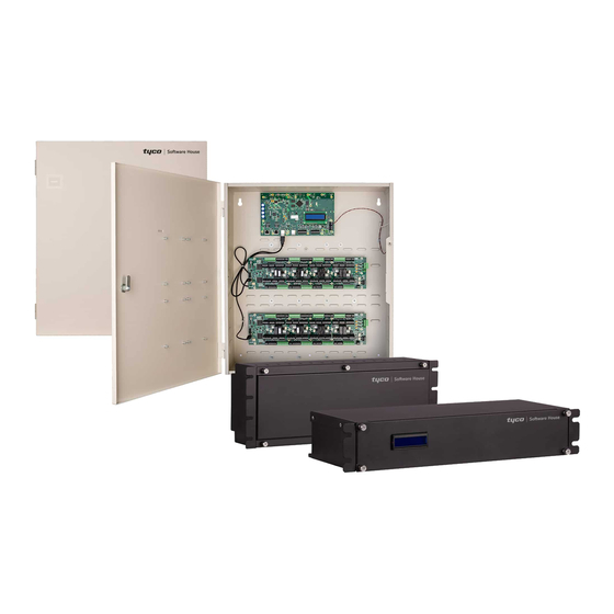
Types of Mounting Types of Mounting The iSTAR Ultra and its components can be installed in a wall mount enclosure or in separate rack mount enclosures. Wall Mount Enclosure Figure 1-1 on page 1-4 shows a photograph of the iSTAR Ultra and two ACMs in a wall mount enclosure. -
Page 19: Rack Mount Enclosures
Types of Mounting Rack Mount Enclosures Figure 1-2 on page 1-5 shows the GCM in a rack mount enclosure. Figure 1-2: GCM Rack Mount Enclosure Figure 1-3 on page 1-5 shows the rear of the GCM rack mount enclosure. Figure 1-3: GCM Rear Rack Mount Enclosure iSTAR Ultra Installation and Configuration Guide 1–5... -
Page 20: Istar Ultra
Types of Mounting iSTAR Ultra Figure 1-4 shows the iSTAR Ultra enclosure. The bright power LED will shine through the Power decal when the door is closed. The bright LED will extinguish when the door is opened. Figure 1-4: STAR Ultra Enclosure 1–6 iSTAR Ultra Installation and Configuration Guide... -
Page 21: Main Features
Main Features Main Features Processor Freescale i.MX6 ARM processor, 1GHz Storage 2GB DDR3 RAM 16GB SD Card Power Powered by 12 Vdc, from UL Listed apS power source or other UL 603 Listed, power- limited power supply with appropriate ratings and a minimum 4 hours of standby power. Provides up to 1.5A @ 12Vdc unswitched to external devices: ... -
Page 22: Aperio Hubs And Readers (Per Gcm Rs-485 Comm Port)
Main Features Two relay Outputs One AUX output (12 Vdc)* * The AUX power and whichever reader power is used, are limited to a total of 1.5 Amp. Aperio Hubs and Readers (per GCM RS-485 Comm Port) An iSTAR Ultra GCM RS-485 Port supports a total of up to: 15 Aperio Hubs ... -
Page 23: I/O (Per Gcm)
Main Features 1 USB 2.0 Port for communication to the GCM. I/O (per GCM) RS-485 Comm Ports • 2 four-pin Ports for Aperio Hubs USB 2.0 Ports • 4 USB host port. • The only use of USB in the first version is to connect to the ACMs and to import encryption keys. -
Page 24: Housing
Part Numbers Switch for ACM address, unit 0 or unit 1. Switch for FAI Enable. Switch for FAI Latch Enable. Switch for AES Encryption. Jumpers for relay wet/dry control. Switch for Backup/Restore. Housing Rack mount Enclosures ... - Page 25 Site Requirements and Installation This chapter provides information about site requirements and installation for the iSTAR Ultra hardware. In This Chapter: Pre-Installation Planning and Requirements ....................2-2 Power Requirements............................2-7 Other Interactions with the Power System....................2-12 Reader Power Requirements ........................
-
Page 26: Pre-Installation Planning And Requirements
Pre-Installation Planning and Requirements Pre-Installation Planning and Requirements Pre-installation involves the following: 1. Checking equipment (hardware, software, power supply, and wiring). 2. Checking power, wiring, equipment clearances, and code compliance at the site. 3. Ensuring the proper tools are available. Equipment Check Verify that the contents of the shipped boxes match the packing lists. -
Page 27: Grounding Requirements
Pre-Installation Planning and Requirements All preliminary site work is complete. System power needs to be 12 Vdc. Appropriate circuit breakers must be accessible. Power supplies must be listed to UL-603 or UL-294. he site is clean and free of dust or other contaminants. ... - Page 28 Pre-Installation Planning and Requirements Table 2-2: Equipment Wiring Specifications, continued Belden # Max. Wire Signal From or equiv. Shield Length Resistance 8.4 RJ45-Ethernet iSTAR Hub, Host Shielded 328 ft. (100 Ultra Cat-5E or better Supervised iSTAR Input 8442/8461 22/18 2000 ft.
-
Page 29: Heat Dissipation
Pre-Installation Planning and Requirements Heat Dissipation Table 2-3 page 2-5 lists the heat dissipation for the rack and wall mount configurations. Table 2-3: Heat Dissipation Power Dissipated in Configuration Enclosure BTU/hour Rack GCM 17.88 Watts 61.0 Rack ACM 6 Watts 20.5 Wall GCM and (1) ACM 23.88 Watts... - Page 30 Pre-Installation Planning and Requirements Table 2-5: Wall Mount Hardware Recommendations Screw Size (Minimum) Concrete, Minimum Screw Type Wood Studs, Drywall Plaster Brick, or Block Number of Anchor Type (Pan Head) Plywood Wall Board Wall Screws No Anchor Wood Screws #10 x 1-1/4 inch No Anchor Concrete Screws #10 x 1-1/4 inch...
-
Page 31: Power Requirements
Power Requirements Power Requirements Electrical This section provides the power requirements for the iSTAR Ultra and its components. Electrical ratings are dependent upon the configuration. Power Input (12 Vdc ± 20%) 12 Vdc , 1.5A minimum, 4.5A maximum (if fully loaded) Power Output ... -
Page 32: Maximum Power
Power Requirements Maximum Power The ISTAR Ultra system power ratings are listed in Table 2-6 through Table 2-8. Table 2-6: iSTAR Ultra GCM Rack System Ratings Local External Current Voltage Circuit Breaker (Vdc) Rating (A) System Description System Power Ratings: 4.49 (1) GCM with (2) RS-485 Loads Table 2-7: iSTAR Ultra ACM Rack Ratings... -
Page 33: Additional Power Requirements
Power Requirements Table 2-8: iSTAR Ultra Wall Mount Ratings, continued Local External Voltage Current Circuit Breaker (Vdc) Rating (A) System Description 10.49 (1) GCM with (2) RS-485 Loads & (1) ACM with (4) Wiegand/RS485/Aux load 15.49 (1) GCM with (2) RS-485 Loads & (1) ACM with (7) Wiegand/RS485/Aux load 18.99 (1) GCM with (2) RS-485 Loads &... -
Page 34: Battery
Power Requirements FOR BURGLAR ALARM INSTALLATIONS: The iSTAR Ultra is not provided with backup power. An external power supply must be provided with the following characteristics: • UL 603 or UL 294 Listed • Minimum four hours of standby power Tyco / Software House Advanced Power Supply (apS) meets these requirements. - Page 35 Power Requirements Table 2-9: Maximum Heat Dissipation, continued Power Dissipated in Configuration Enclosure BTU/hour Wall GCM and (1) ACM 23.88 Watts 81.5 Wall GCM and (2) ACMs 29.88 Watts 102.0 ELECTROSTATIC SENSITIVE DEVICES: Observe precautions for handling. Before handling any internal components, discharge static electricity by ...
-
Page 36: Other Interactions With The Power System
Other Interactions with the Power System Other Interactions with the Power System All of iSTAR Ultras other interactions with the power system are essentially informational in nature and do not directly affect iSTAR Ultra behavior with regard to power loss, power saving and backup. -
Page 37: Reader Power Requirements
Reader Power Requirements Reader Power Requirements This section lists the power requirements for the readers. Software House Readers Table 2-10 page 2-13 shows power requirements for Software House readers. Table 2-10: Software House Reader Power Requirements Reader Model Numbers Current Draw at 12 VDC RM with Multi-Technology Reader RM1-4000, RM2-4000 300 mA max... -
Page 38: Third Party Readers
Reader Power Requirements Table 2-10: Software House Reader Power Requirements, continued Reader Model Numbers Current Draw at 12 VDC Rhino INN-RHNO 1000mA max INN-RHNO-OD INN-RHNO-XT INN-RHNO-XS INN-RHNO-XS-OD INN-RHNO-XSODW INN-RHNO-XS-XT In Table 2-10, indicates readers that have not been evaluated for use with the iSTAR Ultra. All other readers in Table 2-10 are UL Listed compatible readers that can be used with the iSTAR Ultra. -
Page 39: Installation
Installation Installation This section assumes that the site meets the requirements. The iSTAR Ultra does not include mounting hardware. The mounting hardware depends on the site, and must be approved by a structural engineer or other certified professional. See Table 2-5 page 2-6 for more detail. - Page 40 Installation 2. Open the enclosure door and disconnect the grounding wire on the door. 3. Carefully lift the door off the hinges, and place it on a padded surface. 4. Verify that the upper mounting screws (or equivalent) are in place on the mounting site for the keyhole locations.
-
Page 41: Rack Mount Installation
Installation 9. Secure the power inputs with zip-ties to maintain minimum safe distance for electrical safety. Install in accordance with local and national regulations. Non-limited power supply lines must maintain a minimum of 1/2” spacing from limited power supply lines and other signaling lines. -
Page 42: Ip-Acm Installation
Installation IP-ACM Installation The IP-ACM is mounted separately from the Ultra GCM in a plastic or metal enclosure. The following sections describe the enclosures and their installation with the IP-ACM board. NOTE See the IP-ACM Ethernet Door Module Quick Start Guide for power and cabling requirements. -
Page 43: Metal Enclosure
Installation For a UL installation the power must be approved to UL-294 and/or UL-603. To Install the IP-ACM and Plastic Enclosure: 1. Remove the screws using the Software House security screwdriver and lift the enclosure cover off of the plastic IP-ACM enclosure. 2. - Page 44 Installation Table 2-13: IP-ACM Metal Enclosure Dimensions Item Dimension Weight ~2.6lb (~1.2kg) Height 8.25in (209.6mm) Width 7.34in (186.5mm) Depth 3.46in (87.8mm) To Install the IP-ACM and Metal Enclosure: 1. Open the door of the IP-ACM metal enclosure. 2. Secure the enclosure to selected wall or support surface using holes provided in the enclosure’s base.
- Page 45 iSTAR Ultra Network Topology This chapter provides an overview of iSTAR Ultra topology and configuration options. iSTAR Ultra configurations vary according to site requirements. You must understand iSTAR Ultra topology and customer requirements to ensure the correct layout, connections, and configuration of iSTAR Ultra components.
-
Page 46: Chapter 3 Istar Ultra Network Topology
iSTAR Ultra Network Topology iSTAR Ultra Network Topology iSTAR Ultra supports communications over 10/100/1000 Mbps Ethernet networks using TCP/IP. LAN and WAN Configurations The TCP/IP protocol transfers data across a number of networks. Because iSTAR Ultra controllers use the TCP/IP protocol for network communications, they can communicate with each other within a LAN or across a WAN, as shown in Figure 3-1. -
Page 47: Local Address Management
iSTAR Ultra Network Topology Table 3-1: TCP Ports, continued Destination Port Description Protocol System 2008 iWATCH connection port. Not open by default, but can be iWATCH enabled via web page diagnostic settings. 28004 Used to accept signed certification for encryption. Encryption 28009 iSTAR Ultra incoming encrypted member connection port. -
Page 48: Ip Management Tools
iSTAR Ultra Network Topology Figure 3-2: Locked iSTAR Ultra Configuration Example Member 213.112.60.2 213.112.60.2 (exposed) (locked) C•CURE iSTAR host Master Firewall/ Firewall/ 168.54.24.5 172.54.12.6 Gateway (local) Gateway (local) Member Branch Office Corporate Office IP Management Tools iSTAR Ultra controllers can be configured to accept IP addresses and device names from one of the following: Local DHCP ... -
Page 49: Cluster Configuration
Cluster Configuration Cluster Configuration iSTAR Ultra controllers are organized for network communications into user-defined, logical groups called clusters iSTAR controllers must belong to a user-defined group called a cluster. It is possible to have from one to sixteen controllers in a cluster. One of the controllers is designated as the Master and the Master acts as a relay agent to the Host for all of the controllers in the cluster. - Page 50 Cluster Configuration Figure 3-3: Cluster Member Communications Cluster Member A to Host Cluster Member A to Member B Host Host Network Ethernet Cluster Member B Master Cluster Member B Cluster Member A Master Cluster Member A 3–6 iSTAR Ultra Installation and Configuration Guide...
-
Page 51: Master Configurations
Master Configurations Master Configurations To ensure continuous connection, the iSTAR Ultra cluster can communicate with C•CURE using a primary and optional communication secondary path, configured on a single master controller. Figure 3-4 shows primary and secondary communications using a single master. Figure 3-4: Single Master Configuration Single Master Configuration Host... -
Page 52: Communication Paths
Communication Paths Communication Paths The master controller connects to the host over a primary communication path. An optional secondary path can be configured to ensure continuous host communication. Primary Communications Path The primary path is the first communication path that clusters use to establish communications with the host. -
Page 53: Secondary Communications Path
Communication Paths Secondary Communications Path A secondary path is the host communications path that is used by a cluster if a communications failure occurs on the primary path. Figure 3-6 on page 3-9 shows an example of a secondary path on a single master configuration using two network connections. -
Page 54: Maintaining Cluster Communication
Maintaining Cluster Communication Maintaining Cluster Communication Maintaining cluster communications involves establishing and maintaining connections via the primary communication path or (optional) secondary communication path. If the primary connection is lost, the secondary communication path is used to re-establish cluster communications. Single Master Configurations If a configuration with a single master loses its connection with the host, as shown in Figure 3-7 on... -
Page 55: Adding Controllers To The Cluster
Adding Controllers to the Cluster Adding Controllers to the Cluster Follow these guidelines when adding controllers to a cluster. A controller must be assigned to a cluster before the controller can communicate with the host, master, or other controllers. Use the Cluster window in the C•CURE System Administration Application to add controllers to a cluster. -
Page 56: Configuring Communication Paths
Configuring Communication Paths Configuring Communication Paths This section includes guidelines and procedures for configuring primary and secondary communication paths. Planning Primary Communications Configuring a primary communication path involves: Specifying a master for the cluster Specifying a communication methods between the master and the C•CURE host. ... - Page 57 General Control Module (GCM) This chapter describes the GCM switches, buttons, jumpers, LEDs, and the LCD. In This Chapter: General Control Module ..........................4-2 Switches ................................4-3 Ports..................................4-8 Visual Indicators............................... 4-8 iSTAR Ultra Installation and Configuration Guide 4–1...
-
Page 58: Chapter 4 General Control Module (Gcm)
General Control Module General Control Module 4–2 iSTAR Ultra Installation and Configuration Guide... -
Page 59: Network Connections
Switches Network Connections Connect a shielded CAT-5E, or better, RJ45 cable to either J5 J6 (or both for redundancy). J5 Ethernet up to 1 Gbps (10, 100, 1000) J6 Ethernet up to 1 Gbps (10, 100, 1000) There are built in LEDs in the connectors that indicate the Ethernet Link and Receive Data signals. -
Page 60: Sw3 Rotary Switch
Switches SW3 Rotary Switch SW3 is an onboard 16-position rotary switch. Most of the positions are used to control LCD diagnostics. Table 4-1 on page 4-4 provides descriptions of the iSTAR Ultra rotary switch functions. Table 4-1: iSTAR Ultra Rotary Switch Functions Position Description ICU Block Off (Read/Write/Update) Display General Messages... -
Page 61: S1-2- Cpni
Switches If non-encrypted, the iSTAR Ultra controller can cluster with: iSTAR Ultra LT with the Encryption Switch set to OFF Other iSTAR Ultras and Ultra SE (Ultra Mode) with the Encryption Switch set to OFF iSTAR Pros iSTAR Encryption Mode is required to implement FIPS 140-2 (future feature). -
Page 62: Ac Fail Input
Switches Figure 4-1: AC Fail - Low Battery J2 AC Fail Input Indicates whether the external power source has reported loss of its main power. Shares the connector and Ground pin with Low Battery. Normally closed dry relay contacts are required. This signal is normally wired to the ... -
Page 63: Gcm Power - J4
Switches Figure 4-2: Tamper -J1 The tamper switch controls many LEDs, to preserve power and also turns off the super bright LED when the door is open. When the door is opened the small power LEDs are on. The LCD is also off when the door is closed. -
Page 64: Ports
Ports Ports RS-485 1 and 2 (J12 and J13) Used for Aperio Hubs and Schlage PIMs. Each Port can support up to fifteen Hubs. Each Hub can support either one Reader or eight Readers. USB Type A - J8 and J9 Four type A ports used to communicate with ACMs and to import encryption keys from a Certificate Authority using a thumb flash drive. -
Page 65: Leds
Visual Indicators IP address of Host or Master Name of the iSTAR Ultra and MAC address of the NIC IP address of iSTAR Ultra Voltage Member or Master with Date and Time Configured Power and Measured Power ... - Page 66 Visual Indicators 4–10 iSTAR Ultra Installation and Configuration Guide...
- Page 67 Access Control Module (ACM) This chapter explains the ACM switches, buttons, jumpers, LEDs, and the LCD. The wiring of various external connections are also shown. In This Chapter: Access Control Module ........................... 5-2 Inputs ................................5-18 FAI Connections ............................. 5-24 ...
-
Page 68: Access Control Module
Access Control Module Access Control Module The ACM provides Readers, Inputs and Outputs used in access control. An iSTAR Ultra contains either one or two ACMs. Figure 5-1 on page 5-3, Figure 5-2 on page 5-4, and Figure 5-3 on page 5-5 show ACM components, switches, and LEDs. - Page 69 Access Control Module Figure 5-1: ACM Layout USB to GCM Power In Figure 5-2 on page 5-4 indicates all of the components of sections 1 and 8. This pair is typical of the other 3 pairs. It also shows the Power IN ports and the FAI inputs and controls. iSTAR Ultra Installation and Configuration Guide 5–3...
- Page 70 Access Control Module Figure 5-2: ACM Right Side- Sections 1 and 8 The various user visible controls, connectors and displays are shown. Sections 1 and 8 are indicated on most of the components. The jumper technique for wet or dry relays is shown on the left.
-
Page 71: Switches And Jumpers
Access Control Module Figure 5-3: ACM - Left Side Switches and Jumpers SW10 - ACM MCU Reset SW10 reboots both MCUs. It should only be used when it seems the ACM is not responding. J1 USB Type B 2.0 Port Communication link to the GCM. -
Page 72: Rs - 485 Terminators
Access Control Module Examples: One ACM: • S2 OFF • S1 OFF Two ACMs: • ACM 1 - S2 OFF, S1 OFF • ACM 2 - S2 OFF, S1 ON RS - 485 Terminators SW29, SW28, SW14, SW12, SW15, SW25, SW24, SW27 These switches are set to ON by default, and are not usually changed. -
Page 73: Activate On Fai
Access Control Module Activate on FAI SW2, SW4, SW22, SW19, SW18, SW6, SW26, SW23 The Primary relays (large, mounted in sockets) can be configured to Activate when the FAI signal goes true. FAI on this ACM - SW31 There are identical FAI controls on all ACMs. Set this switch to ON on the ACM that is sensing the FAI and KEY signals. -
Page 74: Lock 1 Power - J2
Access Control Module Figure 5-5: Reader Power - Observing Polarity LOCK 1 Power - J2 This is one of the power inputs to the relay outputs that are jumpered as Wet LOCK 1. It can be either 12 Vdc or 24 Vdc. It will also supplement the J4 Reader Power. LOCK 2 Power - J3 This is one of the power inputs to the relay outputs that are jumpered as Wet LOCK 2. -
Page 75: Wiegand Connections
Access Control Module Wiegand Connections J16, J25, J31, J78, J79, J80, J22, J28 Direct Wiegand signaling read head connections are shown in Figure 5-7 on page 5-9. Figure 5-7: Wiegand Readers The data line maximum lengths are: 18 AWG - 500 feet ... -
Page 76: Wiegand Port Rating
Access Control Module Wiegand Port Rating The ACM Wiegand ports and their ratings are listed in Table 5-2 on page 5-10. Table 5-2: ACM Wiegand Port Ratings Port Rating Reader Output Control 4.0v - 5.25v, 20mA max (Red, Green, Yellow, Beeper) Reader Input Lines Low level <... - Page 77 Access Control Module Figure 5-8: HID and aptiQ Reader Wiring iSTAR Ultra Installation and Configuration Guide 5–11...
-
Page 78: Aux Outputs
Access Control Module AUX Outputs The AUX outputs can supply 1.5A for motion sensor or PIR type devices. The voltage is 12 Vdc. See Figure 5-9 on page 5-12 for AUX wiring. Figure 5-9: AUX Wiring Wire the switch contacts of the PIR to one of the iSTAR Ultra inputs, using the proper resistor supervision. -
Page 79: Relay Outputs
Access Control Module Figure 5-11: NO and NC Wiring This method reports: Short Alert (500 ohms) Normal (1K) Alert (2K) Open (>30K) Line Fault (Any unexpected value) Usually due to wrong value resistors or faulty ... -
Page 80: Dry Relay Wiring
Access Control Module • Form C Jumper for each relay to select Wet/Dry and Wet power source It is convenient to configure a Door with all the components together in one of these sections, but it is not a requirement. However, all door components must come from the same controller. -
Page 81: Wet Wiring For A Magnetic Lock
Access Control Module Figure 5-13: Wet NO Latch Wet Wiring for a Magnetic Lock Magnetic Locks are normally energized so the GND and NC pins are used in this case. Notice that jumper is in the Wet position, as shown in Figure 5-14 on page 5-15. - Page 82 Access Control Module Table 5-4: ACM LED Functions, continued Function Comment Relays DS13 Relay 2 Activated Primary Relay DS14 Relay 1 Activated Primary Relay DS31 Relay 5 Activated Primary Relay DS30 Relay 6 Activated Primary Relay DS34 Relay 4 Activated Primary Relay DS35 Relay 3 Activated...
- Page 83 Access Control Module Table 5-6: Wiegand Port LEDs (Lower Set) Power DS49 DS48 DS47 DS55 DS44 DS41 DS26 DS46 DS43 DS42 DS24 DS45 Table 5-7 on page 5-17 summarizes the RS-485 LEDs for Power, Tx, and Rx. Table 5-7: ACM RS-485 LED Functions RS-485 Connector LED - Tx...
-
Page 84: Inputs
Inputs Inputs There are 24 onboard inputs, in sets of three, available on the ACM. Pins 2, 4, and 6 of the Input connectors are common Ground. Figure 5-15: iSTAR Ultra Inputs The type of supervision is configured in the host. Supervision Modes are listed in Table 5-8 on page 5-18. - Page 85 Inputs Table 5-8: Supervision Modes, continued Mode Comment 1K Single Parallel NO Parallel Resistor Normal = 1K Alert = short (0 Ω) 5K Dual NO/NC Wire with Parallel/Serial for NO and Serial/Parallel for NC. Normal = 5K NO Alert = 2.5K ...
- Page 86 Inputs Table 5-8: Supervision Modes, continued Mode Comment 200/10K Double NO Parallel and Serial Resistors (Infographics) Normal = 10K Alert = 196 Casi-Rusco 1K Double NC ( Serial and Parallel Resistors Normal = 1K Alert = 2K ...
-
Page 87: No/Nc Dual Eol 1K
Inputs NO/NC Dual EOL 1K Figure 5-16 on page 5-21 shows the traditional Software House method of supervision where is considered Secure and 500 are considered Alert. Notice that the wiring is different for NO and NC. Figure 5-16: NO / NC Dual EOL 1K For UL Listed products, burglar alarms must be supervised. -
Page 88: Double Eol 1K, 5K, 10K
Inputs Figure 5-17: NO / NC Dual EOL 5K, 10K For UL Listed products, burglar alarms must be supervised. For the remainder of the choices you have to choose either NO or NC. Double EOL 1K, 5K, 10K Figure 5-18: Dual EOL 1K, 5K, 10K For UL Listed products, burglar alarms must be supervised. -
Page 89: Single Eol 5K, 10K
Inputs Single EOL 5K, 10K Figure 5-19: Single EOL 5K, 10K For UL Listed products, burglar alarms must be supervised. Non-Supervised Figure 5-20: Non-Supervised For UL Listed products, burglar alarms must be supervised. iSTAR Ultra Installation and Configuration Guide 5–23... -
Page 90: Fai Connections
FAI Connections FAI Connections FAI Scenarios FAI (Fire Alarm Interlock) is a hardware feature that will activate all enabled relays when the F input of J84 opens. It is NC (Normally Closed). The concept of activating relays when a fire is signaled can be used in two basic scenarios: Unlock all doors when fire is present. -
Page 91: Fai With Latch Followed By Key Unlatch
FAI Connections Figure 5-21: FAI without Latch FAI with Latch followed by Key Unlatch If the Latch Enable switch (SW30) is on and the F input goes true the selected relays will activate and stay that way until an Unlatch is given. 1. -
Page 92: F And K Input Supervision
FAI Connections Figure 5-22: FAI with Latch F and K input Supervision Although the F and K inputs will work when they are unsupervised, as shown in Figure 5-21 page 5-25 and Figure 5-22 on page 5-26, Software House recommends that you use the standard Software House method of supervising the inputs. -
Page 93: State Of F, K, And Relay Drive
FAI Connections State of F, K, and Relay Drive In addition to the added security gained by using supervision, the state of F, K, and Relay Drive signals will be available in the C•CURE system. All three of the inputs, shown in Figure 5-24 on page 5-27, support event triggers based on their active or inactive states. -
Page 94: Istar Controller Status Tab
FAI Connections iSTAR Controller Status Tab The iSTAR Controller dialog box Status tab in the C•CURE 9000, shown in Figure 5-25 on page 5-28, indicates encryption status plus other read-only information about the Ultra. Figure 5-25: Controller Dialog Box- Status Tab 5–28 iSTAR Ultra Installation and Configuration Guide... -
Page 95: Reader - Voltage Requirements And Distance
Reader - Voltage Requirements and Distance Reader - Voltage Requirements and Distance To operate properly, each reader requires the following minimum voltage: A standard RM Series Reader or RM-4 board requires at least 7.5 volts An RM-4E board requires at least 11 volts ... - Page 96 Reader - Voltage Requirements and Distance Table 5-9: Equipment Wiring Specifications Belden # Max. Wire Signal From or equiv. Shield Length Resistance RS-485 Comm, Data iSTAR Ultra RM & I/O 9841 4000 ft. 103 Half-duplex 2 wire Modules (1212 m) RS-485 Comm, Power iSTAR Ultra RM &...
-
Page 97: Readers And Accessory Boards
Readers and Accessory Boards Readers and Accessory Boards The following readers and accessory boards are supported: Wiegand Signaling Readers: • SWH-4000 • SWH-4200 • SWH-4100 • SWH-5100 • P345KPMTR • HID 5365 series • HID RP40 multiCLASS • HID RPK40 multiCLASS •... - Page 98 Readers and Accessory Boards 5–32 iSTAR Ultra Installation and Configuration Guide...
-
Page 99: Ip-Acm Ethernet Door Module V2
IP-ACM Ethernet Door Module v2 This chapter provides an overview of the IP-ACM Ethernet Door Module v2. For more information regarding the specifications, features, and installation of the IP-ACM, refer to the IP-ACM Ethernet Door Module v2 Quick Start Guide. In This Chapter: Overview ................................ -
Page 100: Overview
Overview Overview The IP-ACM Ethernet Door Module v2, Figure 6-1 on page 6-3, provides connection and management of access control for two readers. The maximum number of IP-ACM Ethernet door modules supported per iSTAR Ultra is 32. Each IP-ACM can support two doors, or one door with in and out readers. - Page 101 Overview Figure 6-1: IP-ACM Ethernet Door Module v2 iSTAR Ultra Installation and Configuration Guide 6–3...
- Page 102 Overview 6–4 iSTAR Ultra Installation and Configuration Guide...
- Page 103 iSTAR Ultra Controller Configuration This chapter describes the iSTAR Ultra controller configuration and diagnostics. In This Chapter: iSTAR Ultra Initial Configuration........................7-2 STAR Ultra Local Database Backups ......................7-6 Proper Shutdown Sequence..........................7-6 Firmware Upgrades ............................7-7 ...
-
Page 104: Istar Ultra Initial Configuration
iSTAR Ultra Initial Configuration iSTAR Ultra Initial Configuration The initial configuration of the iSTAR Ultra brings the board online and provides the board with an IP address. Initial Configuration Guidelines The Ultra GCM board has two Ethernet ports, either of which can be set to DHCP or static IP addresses. - Page 105 iSTAR Ultra Initial Configuration To configure the controller to use a Static IP address: 1. Remove all network cables from the controller. 2. Turn rotary switch (SW3) to position 'D' and press the reset button (SW7) or cycle power. 3. Wait until the LCD says to reset the board. 4.
-
Page 106: Initial Panel Discovery
iSTAR Ultra Initial Configuration Initial Panel Discovery The initial configuration of the iSTAR Ultra brings the board online and provides the board with an IP address. Controllers with firmware v6.6.B or higher can only use ICU v6.6.B, and for initial discovery only. -
Page 107: C•Cure 9000
iSTAR Ultra Initial Configuration The iSTAR Ultra log in screen opens in the default browser. 2. Enter the password and click LOG IN. NOTE The default case-sensitive password is "iSTAR". 3. The iSTAR Ultra Welcome page opens in the default browser. Click to open the About information box and select Help to open the iSTAR Ultra ... -
Page 108: Star Ultra Local Database Backups
STAR Ultra Local Database Backups See the C•CURE 9000 Hardware Configuration Guide and the C•CURE 9000 help for more information. STAR Ultra Local Database Backups If CPNI mode is enabled on the iSTAR Ultra, then all database and transactions are stored in NOTE RAM. -
Page 109: Firmware Upgrades
Firmware Upgrades 5. The LCD display goes black for about five seconds. In this time, remove the power cable from the Ultra GCM board. • If you miss the opportunity to remove the power cable from the iSTAR Ultra GCM and it begins the boot-up sequence again, you must wait for a full boot-up cycle to complete and repeat the steps above before you remove the SD card. - Page 110 Firmware Upgrades 7–8 iSTAR Ultra Installation and Configuration Guide...
-
Page 111: Maintenance
Maintenance The iSTAR Ultra includes an LCD message display. For normal operations, configure the LCD to display status messages. For troubleshooting operations, configure the LCD to display diagnostic messages about readers, card data, inputs, outputs, network ports and devices. In This Chapter: LCD Message Display ............................. -
Page 112: Lcd Message Display
LCD Message Display LCD Message Display The iSTAR Ultra includes an LCD display for status and diagnostic messages. SW3 is an onboard 16-position rotary switch. Most of the positions are used to control LCD diagnostics. Figure 8-1 shows the location of the rotary switch SW3. See Table 8-1 on page 8-2 for a summary of SW3 settings. -
Page 113: Displaying Status Messages
LCD Message Display Table 8-1: iSTAR Ultra Rotary Switch Functions, continued Position Description Hardware Test (Onboard Ethernet 1 and 2, USB ports). NOTES: Ethernet tests require a good IP (Static or DHCP, and a good network link) and at least ... -
Page 114: Diagnostic Tests
Diagnostic Tests Table 8-2: LCD Status Display Messages Rotary Display General Display General Messages Switch Messages (Read only) (Read/Write/Update) ICU Block On ICU Block Off Set SW3 to: Diagnostic Tests iSTAR Ultra firmware provides diagnostic information for: Readers Cards ... -
Page 115: Card Reader Diagnostics
Diagnostic Tests The LCD displays only success messages. If no message displays, the circuit is defective or the port is not communicating. Card Reader Diagnostics You can display the most recent card data processed by any reader on iSTAR Ultra in either fast mode or slow mode. -
Page 116: Ethernet Port Test
Diagnostic Tests Information displays on the LED for either one second (Position 4, On) or two seconds (Position 3, On). To Activate Input Change Display Tests Set the SW3 rotary switch to the positions shown in Table 8-6. Table 8-6: Input Test Switch Settings Switch Position Function SW3 set to 3... -
Page 117: Gcm Battery Replacement
GCM Battery Replacement GCM Battery Replacement The GCM coin cell battery should be tested annually and replaced as necessary. The battery is a CR2032 Lithium 230 mA/h coin cell. The battery retains power for the Real Time Clock for at least 3 weeks. After three weeks ... - Page 118 GCM Battery Replacement 8–8 iSTAR Ultra Installation and Configuration Guide...
Need help?
Do you have a question about the tyco iSTAR Ultra and is the answer not in the manual?
Questions and answers