Table of Contents
Advertisement
Available languages
Available languages
Quick Links
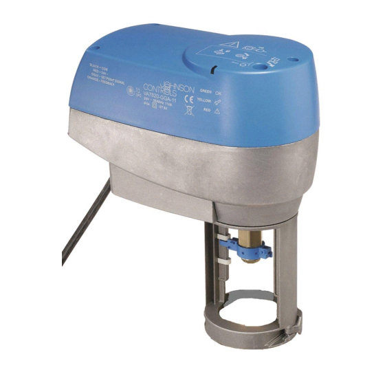
VA7820-HGx-2 / VA7830-HGx-2
Electric Valve Actuators - Spring Return Models
Installation Guide
Johnson Controls, Inc.
Headquarters:
Milwaukee, Wisconsin, USA
Branch Offices: Principal Cities World-wide
VA7820-HGx-2 / VA7830-HGx-2
Figure 1: Dimensions in inches (mm)
P/N 14-88375-92 Rev. A
Issue Date 01 2009
Advertisement
Table of Contents

Related Manuals for Johnson Controls VA7820-HG 2 Series


Summary of Contents for Johnson Controls VA7820-HG 2 Series
- Page 1 VA7820-HGx-2 / VA7830-HGx-2 Electric Valve Actuators - Spring Return Models P/N 14-88375-92 Rev. A Issue Date 01 2009 Installation Guide VA7820-HGx-2 / VA7830-HGx-2 Figure 1: Dimensions in inches (mm) Johnson Controls, Inc. Headquarters: Milwaukee, Wisconsin, USA Branch Offices: Principal Cities World-wide...
- Page 2 Figure 2: Mounting Positions Figure 3: Manual Positioner Figure 4: Mounting Actuator on the valve VA7820-HGx-2 / VA7830-HGx-2...
- Page 3 Figure 5: Wiring Diagrams Figure 6: Starting self-calibration Figure 7: Auxiliary switches setting VA7820-HGx-2 / VA7830-HGx-2...
- Page 4 English This document is subject to change without notice READ THIS INSTRUCTION SHEET AND THE SAFETY WARNINGS Wiring CAREFULLY BEFORE INSTALLING AND SAVE IT FOR FUTURE USE WARNING: Risk of Electric Shock. General Features Disconnect each of the multiple power supplies before making electrical connections.
- Page 5 LED will illuminate a steady damage to the equipment. green. • Do not repair or replace a damaged cable, contact the nearest Johnson Controls® • If the control signal changes, the actuator stem will move to the new position. commercial system wholesaler.
- Page 6 Français Ce document peut être sujet à des modifications sans préavis LISEZ ATTENTIVEMENT LA PRÉSENTE FICHE D’INSTRUCTIONS, Figure 4 : Montage de la commande sur la vanne AINSI QUE LES AVERTISSEMENTS RELATIFS À LA SÉCURITÉ, AVANT Vérifier que le coupleur se trouve dans la bonne position. Sinon, le réajuster à l'aide de la commande manuelle.
- Page 7 • Ne pas réparer ou remplacer un câble endommagé. Contacter le grossiste systèmes • Une fois la procédure terminée, la commande repasse en mode service et atteint la commerciaux Johnson Controls le plus proche. position correspondant à la valeur du signal d'entrée. Le voyant vert s'allume.
Need help?
Do you have a question about the VA7820-HG 2 Series and is the answer not in the manual?
Questions and answers