Table of Contents
Advertisement
Quick Links
Advertisement
Table of Contents

Related Manuals for cytiva AKTA process


Summary of Contents for cytiva AKTA process
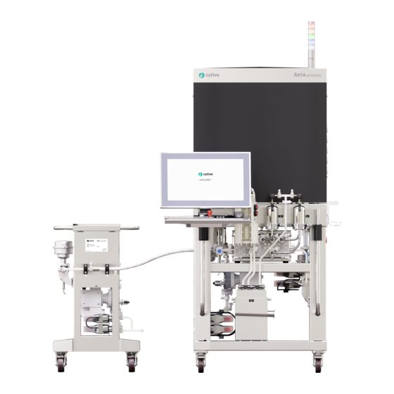
- Page 1 ÄKTA process™ Unpacking Instructions cytiva.com...
-
Page 2: Table Of Contents
Table of Contents Read this before unpacking ÄKTA process ......... 3 On delivery ..................... 5 Tools and equipment ................6 Moving the transport crate ..............7 Unpacking the system ................9 Attach operator console to the system ..........17 Unpack the pump .................. 25 After unpacking .................. -
Page 3: Read This Before Unpacking Äkta Process
Read this before unpacking ÄKTA process This instruction contains information that is important for safety during the unpacking of ÄKTA process™ chromatography system. Read the whole instruc- tion carefully before starting to unpack the system. Scope of the Unpacking Instructions This document describes: •... - Page 4 Working gloves, protecting against sharp edges. • Protective glasses. WARNING ÄKTA process must be installed and prepared by Cytiva personnel or third party authorized by Cytiva. CAUTION The product is partly filled with a storage solution of approximately 20% C OH (ethanol, technical grade) at delivery.
-
Page 5: On Delivery
Transport in crate, on page 7 when moving the crate. Contact your Cytiva representative and inform of the delivery and of any damage that has been observed. Inform also about anything written on the receiving documents concerning transportation damage. Storage site requirements... -
Page 6: Tools And Equipment
Tools and equipment Required tools and equipment The following tools and equipment are required to unpack ÄKTA process system or the additional pump: • Suitable lifting equipment (a forklift, a crane or equivalent) for moving the transport crate • 4 mm hex wrench •... -
Page 7: Moving The Transport Crate
Moving the transport crate Transport in crate Use a pallet jack or forklift with a minimum capacity to match the weight of the system plus the transport crate. WARNING Distributed load. Make sure that the load is evenly distributed over the forks of the lifting equipment. Note: Make sure that intended openings and apertures are large enough to allow passage of the crate when the crate is lifted from the floor for transport. - Page 8 System and crate specifications The following table provides information on system type and weight as well as the weight and dimension of the transport crate. Property ÄKTA process S ÄKTA process L Polypropy- 6 mm 10 mm 1 inch lene System tubing size Stainless...
-
Page 9: Unpacking The System
Unpacking the system WARNING Heavy object. Because of the significant weight of the system, great care must be taken not to cause squeezing or crushing inju- ries during movement. At least two, but preferably three or more, persons are recommended when unpacking or moving the system. Unpack system from crate Step Action... - Page 10 Step Action Each end panel is attached to a side panel by two hinges. Swing open both end panels. Remove the enclosed operator console, accessory, and documentation boxes that are packed separately inside the crate. Unscrew the two screws marked in the illustration below and remove the enclosed loading ramp.
- Page 11 Step Action Secure the ramp to the end of the crate marked with the letter A, as shown below. The ramp should fit closely to the end of the crate. Make sure that the pre-drilled holes in the tabs of the ramp align with the pre-drilled holes in the crate.
- Page 12 Step Action Unscrew and remove the wooden stop blocks at the front of the system, by removing the carriage bolts highlighted in the illustration below. Note: The screws of the stop blocks must be removed to prevent scratching of the system surface when the system is rolled out of the crate.
- Page 13 Step Action Unscrew the four wooden spacers under the system. Unscrew and remove the wooden lever (marked by the arrow in the illustra- tion below) that is attached to the floor of the crate. ÄKTA process Unpacking Instructions 29605009 AD...
- Page 14 Remove system from crate WARNING Heavy object. The ramp is not reinforced in the center. Do not use a pallet lifter or forklift on the ramp. WARNING Heavy object. Take great care to avoid the wheels slipping off the edge of the ramp, especially the higher wheels of ÄKTA process L systems.
- Page 15 Recycle the crates according to local recommendations for pesti- cide treated wood. Check that all equipment is enclosed in the crate according to the packing list. If not, immediately inform your local Cytiva representative. ÄKTA process Unpacking Instructions 29605009 AD...
- Page 16 After unpacking the system, open all boxes of accessories that have been delivered with the system and make sure that all of the items listed on the packing list have been received. • Report any missing or damaged accessory items to your local Cytiva representative. ÄKTA process Unpacking Instructions 29605009 AD...
-
Page 17: Attach Operator Console To The System
Attach operator console to the system Assemble monitor and console arm WARNING Personal Protective Equipment (PPE). When packing, unpacking, transporting or moving the product, wear the following. • Protective footwear, preferably with steel toe-cap. • Working gloves, protecting against sharp edges. •... - Page 18 Step Action Place the padding from the boxes on an even surface, such as a table. Then, carefully place the screen with the monitor facing down on the padding. Pull the monitor cables through the opening of the arm, and then attach the console arm to the screen with four screws.
- Page 19 Step Action Fit the console arm carefully on the system handle. For more information, see Fit the operator console on the right handle, on page 19 Fit the operator console on the left handle, on page 21. Make sure that the console arm is firmly attached.
- Page 20 Step Action The console arm has two pinholes underneath for orienting the arm over the steering pin as illustrated below. To fit the console arm over the rotation stop, rotate the monitor inwards towards the air trap until the arm is aligned over the left steering pin as illus- trated below.
- Page 21 Step Action Carefully lower the console arm over the pin and the rotation stop until it is firmly attached. Fit the operator console on the left handle To fit the operator console on the left handle, follow the instructions in Fit the operator console on the right handle, on page 19, but rotate the monitor inwards towards the air...
- Page 22 Attach console keyboard and cables Follow the steps below to attach the keyboard and cables of the operator console. Step Action Pull the gray cable that is attached to the keyboard through the opening of the console arm. Rest the keyboard on the console arm and connect the white cable to the keyboard.
- Page 23 Step Action Unscrew the black lid on the back of the operator console. Attach the mouse cable to the USB port. Insert any excess cable and reattach the lid. NOTICE The protective screw cap should always be in place when the USB connector is not in use.
- Page 24 Step Action The three cables that are attached to the operator console must be connected to the connectors at the bottom of the electrical cabinet. • Connect the CBL-111 cable to the SDL 4 connector for all signal connec- tions to and from the touchscreen monitor and the keyboard (DVI signal and USB connection).
-
Page 25: Unpack The Pump
Unpack the pump Unpack feed pump or ILD pump WARNING Heavy object. Because of the significant weight of the product, great care must be taken not to cause squeezing or crushing inju- ries during movement. Step Action Place the crate on a hard, horizontal floor with at least 300 cm of free space on the ramp side of the crate. - Page 26 Step Action Remove the ramp panel by tilting the panel outwards approximately 20 degrees to release the panel from the supporting rail. Place the ramp panel near the crate for later use. Lift and remove the top panel of the crate. Remove the accessories box.
- Page 27 Step Action Remove the foam blocks from the top of the pump. Prepare the ramp: a. Place the two ramp supports on the floor on the ramp side of the crate. b. Attach the ramp panel to the ramp side of the crate and align the ramp supports with the guides provided on the ramp panel.
- Page 28 Step Action Remove the foam block from the bottom front of the pump. Carefully roll the pump down the ramp. Make sure that the motion is controlled and that there is ample free space in front of the crate so that the pump does not accidentally hit any object or person.
-
Page 29: After Unpacking
After unpacking Moving after unpacking • The system or the pump can be rolled by hand on hard and level surfaces with the wheel brakes released. • If the floor quality does not allow rolling the system or the pump on its own wheels, suitable lifting equipment must be used to lift and move the system or the pump. - Page 30 Cytiva and the Drop logo are trademarks of Life Sciences IP Holdings Corporation or an affiliate doing business as Cytiva. ÄKTA process is a trademark of Global Life Sciences Solutions USA LLC or an affiliate doing business as Cytiva.
Need help?
Do you have a question about the AKTA process and is the answer not in the manual?
Questions and answers