Table of Contents
Advertisement
Quick Links
Advertisement
Table of Contents
Troubleshooting

Subscribe to Our Youtube Channel
Related Manuals for cytiva AKTA start


Summary of Contents for cytiva AKTA start
- Page 1 ÄKTA start™ Maintenance Manual ÄKTA start UNICORN start cytiva.com...
-
Page 2: Table Of Contents
Table of Contents Table of Contents Introduction ......................4 Important user information ........................5 About this manual ............................6 Associated documentation ........................8 Abbreviations ..............................11 System description .................... 12 System overview ............................13 Instrument ................................ 17 Maintenance operations ..................20 Regular maintenance schedule ....................... - Page 3 Table of Contents Troubleshooting ....................93 UV ..................................94 Conductivity ..............................96 Frac30 ................................97 Pump .................................. 98 Pressure sensor ............................. 99 Main board and Power Supply ........................100 System related error messages ....................... 101 Troubleshooting flow charts ........................102 Replacement procedures ..................
-
Page 4: Introduction
1 Introduction Introduction About this chapter This chapter contains important user information and a list of associated documenta- tion. In this chapter Section See page Important user information About this manual Associated documentation Abbreviations ÄKTA start Maintenance Manual 29060308 AF... -
Page 5: Important User Information
1 Introduction 1.1 Important user information Important user information Introduction This section contains important user information about the product and this manual. Read this before operating the product All users must read the entire Operating Instructions before installing, oper- ating, or maintaining the product. Always keep the Operating Instructions at hand when operating the product. -
Page 6: About This Manual
1 Introduction 1.2 About this manual About this manual Introduction This section contains information about the purpose and scope of this manual, notes and tips, and typographical conventions. Purpose of this manual This manual provides information needed to install, operate and maintain the product in a safe way. - Page 7 1 Introduction 1.2 About this manual Definitions This user documentation contains safety notices (WARNING, CAUTION, and NOTICE) concerning the safe use of the product. See definitions below. WARNING WARNING indicates a hazardous situation which, if not avoided, could result in death or serious injury. It is important not to proceed until all stated conditions are met and clearly understood.
-
Page 8: Associated Documentation
Introduction This section describes the user documentation that is delivered with the product, and how to find related literature that can be downloaded or ordered from Cytiva. User documentation for ÄKTA start The user documentation for ÄKTA start is listed in the table below. - Page 9 To order or download data files, application notes or user documentation, see the instruction below. Step Action Go to cytiva.com/aktastart. Navigate to Related Documents. Select to download the chosen literature. ÄKTA start Maintenance Manual 29060308 AF...
- Page 10 1 Introduction 1.3 Associated documentation Access user documentation online Scan the QR code or visit cytiva.com/instructions. Enter the title or the document number to access the file. eLearning course on-demand An on demand eLearning course is available for the ÄKTA start system. To enroll go to cytiva.com/aktastartelearning.
-
Page 11: Abbreviations
1 Introduction 1.4 Abbreviations Abbreviations Introduction This section explains abbreviations that appear in the user documentation for ÄKTA start. Abbreviations Abbreviation Definition affinity chromatography absorbance unit bitmap file format centipoise (unit of viscosity) column volume demineralized desalting ETFE ethylene tetrafluoroethylene fluorinated ethylene propylene FPGA field-programmable gate array... -
Page 12: System Description
2 System description System description About this chapter This chapter provides an overview of the ÄKTA start instrument, and the optional Frac- tion collector Frac30. For more details, refer to the ÄKTA start Operating Instructions. In this chapter Section See page System overview Instrument ÄKTA start Maintenance Manual 29060308 AF... -
Page 13: System Overview
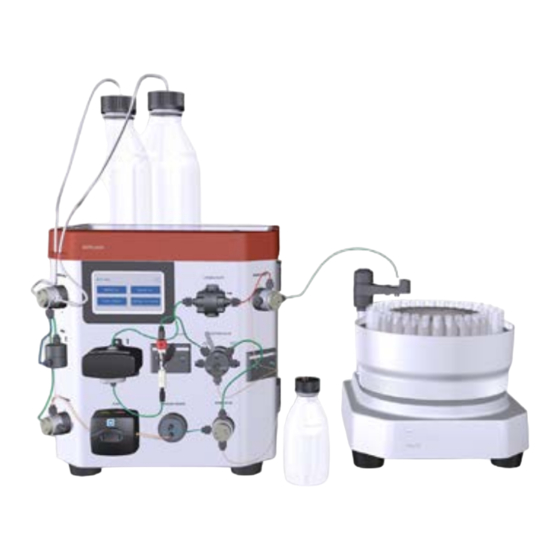
2 System description 2.1 System overview System overview Introduction ÄKTA start is operated and controlled from the Instrument Display. In addition, the UNICORN start software can be used to control ÄKTA start and to analyze the data acquired during chromatography runs. UNICORN start offers several additional features that are described in detail in UNICORN start User Manual. - Page 14 2 System description 2.1 System overview Illustration of the instrument The illustration below shows the main parts of the instrument. Part Description Function Instrument Display User interface for controlling the system and visualization of the runtime data. Wet side The modules interconnected by tubing have the following functions: •...
- Page 15 2 System description 2.1 System overview Part Description Function USB port To connect a USB memory stick for storage of results and transfer of files. Note: USB hard drives are not supported. Illustration of the Fraction collector The illustration below shows the front and rear views of the Fraction collector, Frac30. Note: ÄKTA start does not support fractionation with any fraction collector other than Fraction collector Frac30.
- Page 16 2 System description 2.1 System overview Part Description Function Drive sleeve Friction drive to turn the Bowl assembly during fraction collection. Main features of ÄKTA start The main features of ÄKTA start are listed below: • ÄKTA start is a compact and one step purification solution for quick and reliable purification of proteins.
-
Page 17: Instrument
2 System description 2.2 Instrument Instrument Introduction This section provides an overview of ÄKTA start modules. Illustration of the instrument modules The illustration below shows the locations and gives brief descriptions of the modules placed on the wet side of the instrument. Part Function Description... - Page 18 2 System description 2.2 Instrument Part Function Description Sample valve A 3-port valve that allows either the buffer or the sample to enter the flow path. The Sample valve enables direct application of the sample onto the column using the Pump. Pump A peristaltic pump, which delivers buffer or sample to the flow path with a flow rate of up to 5 mL/min.
- Page 19 2 System description 2.2 Instrument Part Function Description Conductivity The Conductivity Monitor continuously reads the conductivity of the liquid in the Conductivity flow cell. The conductivity is automatically calculated by multiplying the measured conductance by the cell constant of the flow cell. The cell constant is factory-calibrated.
-
Page 20: Maintenance Operations
3 Maintenance operations Maintenance operations About this chapter Regular maintenance of ÄKTA start is essential for reliable function and performance. This chapter provides instructions for periodic maintenance, including calibration and configuration, as well as other required maintenance. In this chapter Section See page Regular maintenance schedule... - Page 21 Cytiva. • Only spare parts and accessories that are approved or supplied by Cytiva may be used for maintaining or servicing ÄKTA start. • Disconnect power. Always switch off power to the instrument before replacing any component on the instrument or cleaning the instrument, unless stated otherwise in the user documenta- tion.
-
Page 22: Regular Maintenance Schedule
3 Maintenance operations 3.1 Regular maintenance schedule Regular maintenance schedule Introduction Regular maintenance must be performed on a daily, weekly and monthly basis. For cleaning instructions, refer to the ÄKTA start Operating Instructions. Daily maintenance The following maintenance operations should be performed daily when the system is in use. - Page 23 3 Maintenance operations 3.1 Regular maintenance schedule Weekly maintenance The following maintenance operations should be performed weekly or when required. Maintenance action See section Calibrate the Pump. Section 3.6.1 Calibration, on page 50 Visually inspect the inlet filters and clean ÄKTA start Operating Instructions them if necessary.
- Page 24 3 Maintenance operations 3.1 Regular maintenance schedule Maintenance action See section Calibrate the Conductivity cell Section 3.11 Conductivity Monitor, on page 68 Pressure sensor zero offset Section 3.12 Pressure sensor, on page 75 Replace the inlet filters ÄKTA start Operating Instructions Replace the tubing and connectors ÄKTA start Operating Instructions ÄKTA start Maintenance Manual 29060308 AF...
-
Page 25: Cleaning Before Planned Service
3 Maintenance operations 3.2 Cleaning before planned service Cleaning before planned service Cleaning before planned maintenance/service To protect the safety of service personnel, all equipment and work areas must be clean and free of any hazardous contaminants before a Service Engineer starts maintenance work. -
Page 26: Access The Modules
3 Maintenance operations 3.3 Access the modules Access the modules Instrument modules The location of modules is shown in Section 2.2 Instrument, on page Software access Maintenance and service of the different modules is managed from the Instrument Display. For instructions about maintenance of a module, see the specific sections in this chapter. - Page 27 3 Maintenance operations 3.3 Access the modules Step Action ÄKTA start Maintenance Manual 29060308 AF...
-
Page 28: Instrument Display
3 Maintenance operations 3.4 Instrument Display Instrument Display Introduction This section describes how to calibrate and test the Instrument display. In this section Section See page 3.4.1 Touch screen calibration 3.4.2 Color test 3.4.3 Diagnostics 3.4.4 Log book Instructions Follow the instructions below to select an option to calibrate and/or diagnose the Instrument display. - Page 29 3 Maintenance operations 3.4 Instrument Display Step Action Result: The Display screen opens. ÄKTA start Maintenance Manual 29060308 AF...
-
Page 30: Touch Screen Calibration
3 Maintenance operations 3.4 Instrument Display 3.4.1 Touch screen calibration 3.4.1 Touch screen calibration Instructions Follow the instructions below to calibrate the Touch screen. Step Action In the Display screen, tap Touch screen calibration. Result: A confirmation screen opens. Tap Yes to proceed with the calibration of the Touch screen. Result: The following screen opens. - Page 31 3 Maintenance operations 3.4 Instrument Display 3.4.1 Touch screen calibration Step Action Result: The following screen opens. Tap precisely on the marked circle 2. Result: The following screen opens. Tap precisely on the marked circle 3. Result: The following screen opens. Tap precisely on the marked circle 4.
- Page 32 3.4 Instrument Display 3.4.1 Touch screen calibration Step Action Result: The following screen opens. Tap Exit. Note: If the calibration fails, repeat the test. If the calibration fails again, contact a Cytiva Service Engineer. ÄKTA start Maintenance Manual 29060308 AF...
-
Page 33: Color Test
Follow the instructions below to test the colors of the Touch screen. Step Action In the Display screen, tap Color test. Result: The following screen opens. Tap Exit. Result: The Color test is completed. Note: If the test fails, contact a Cytiva Service Engineer. ÄKTA start Maintenance Manual 29060308 AF... -
Page 34: Diagnostics
3 Maintenance operations 3.4 Instrument Display 3.4.3 Diagnostics 3.4.3 Diagnostics Instructions Follow the instructions below to perform diagnostics of the Touch screen. Step Action In the Display screen, tap Diagnostics. Result: The following screen opens. In the Select backlight brightness screen, tap a radio button to select the intended brightness (%). -
Page 35: Log Book
The Log Book displays the number of hours the Instrument Display has been used. The number of hours should be reset to zero when the Instrument Display is replaced. Note: The instrument display must be replaced by a Cytiva Service Engineer. Instructions Follow the instructions below to read the Log book for the Display. - Page 36 3 Maintenance operations 3.4 Instrument Display 3.4.4 Log book Step Action Result: A confirmation screen opens. Tap Yes to confirm the reset if the Instrument Display has been replaced. If the Instrument Display has not been replaced, tap No to cancel the action. ÄKTA start Maintenance Manual 29060308 AF...
-
Page 37: Uv Monitor
3 Maintenance operations 3.5 UV Monitor UV Monitor Introduction This section describes how to access the UV Monitor options, perform a calibration, and edit UV settings. In this section Section See page 3.5.1 UV LED calibration 3.5.2 Diagnostics 3.5.3 Flow cell path length 3.5.4 Configuration Access the UV Monitor options... -
Page 38: Uv Led Calibration
3 Maintenance operations 3.5 UV Monitor 3.5.1 UV LED calibration 3.5.1 UV LED calibration Description UV LED calibration is used to calibrate the UV LED intensity to get the desired response level of the photo detector. Parameter Description Light strength Light intensity needed to get the expected response at the photo detector. - Page 39 3 Maintenance operations 3.5 UV Monitor 3.5.1 UV LED calibration Step Action Result: The message Please wait while bias search is being done is displayed When the message UV biasing successful is displayed, press OK. Result: The Light strength value is automatically adjusted to get a minimum Signal response of 2700 mV.
-
Page 40: Diagnostics
3 Maintenance operations 3.5 UV Monitor 3.5.2 Diagnostics 3.5.2 Diagnostics Description Diagnostics is used to conduct a Dark current test and/or a Stray light test to assess electrical noise or presence of stray light. Test Description Dark current test • Switches off the UV LED during the test. •... - Page 41 Make sure that the detector is not exposed to e.g., direct sunlight. If the test fails again, replace the flow cell and then possibly the UV Monitor, or contact a Cytiva Service Engineer. Flush the system with demineralized water so that the Abs value returns close to zero.
-
Page 42: Flow Cell Path Length
3 Maintenance operations 3.5 UV Monitor 3.5.3 Flow cell path length 3.5.3 Flow cell path length Description A Flow cell path length test is used to derive the actual path length of the UV flow cell. The test should be performed when the UV Monitor or the UV flow cell has been replaced, and when normalized UV absorption comparisons between different systems are needed. - Page 43 3 Maintenance operations 3.5 UV Monitor 3.5.3 Flow cell path length Step Action Result: The following screen opens. Set the Cell value to 2.00 mm by using the up/down arrows or enter the value in the text box. Flush the UV flow cell thoroughly and leave it filled with demineralized water.
-
Page 44: Configuration
NOTICE Do not change the C drft and C amb values. These parameters must be set by a Cytiva Service Engineer. Reset number of run hours Follow the instructions below to reset the number of run hours of UV Monitor. Reset the number of run hours when the UV Monitor is replaced. - Page 45 Result: The Configuration screen opens. NOTICE Do not change the C drft and C amb values. These parameters must be set by a Cytiva Service Engineer. Tap Reset. Result: A confirmation screen opens. If the UV Monitor has been replaced, tap Yes.
- Page 46 Action Tap Configuration. Result: The Configuration screen opens. Do not change the C drft and C amb values. These parameters must be set by a Cytiva Service Engineer. Tap Turn UV OFF. Result: A confirmation screen opens. Tap Yes. Result: The UV module is turned off and the Turn UV OFF changes to Turn UV ON.
- Page 47 3 Maintenance operations 3.5 UV Monitor 3.5.4 Configuration Step Action ÄKTA start Maintenance Manual 29060308 AF...
-
Page 48: Pump
3 Maintenance operations 3.6 Pump Pump Introduction This section describes how to perform pump diagnostics and calibration and manage the pump tubing log. In this section Section See page 3.6.1 Calibration 3.6.2 Diagnostics 3.6.3 Pump tubing log Access the Pump service options Follow the instruction below to access the options for Pump calibration and trouble- shooting. - Page 49 3 Maintenance operations 3.6 Pump Step Action Tap to select the intended option. ÄKTA start Maintenance Manual 29060308 AF...
-
Page 50: Calibration
3 Maintenance operations 3.6 Pump 3.6.1 Calibration 3.6.1 Calibration Description The table below describes the parameters for calibrating the Pump. Parameter Description Flow Rate The intended flow rate used for Pump calibration. Collected Volume The volume of liquid collected for a certain period of time at the set flow rate. - Page 51 3 Maintenance operations 3.6 Pump 3.6.1 Calibration Step Action Use the up/down arrows to set the desired Flow Rate. a. Tap Start flow to start the Pump. b. Collect water for at least one minute in the pre-weighed collection tube. c.
-
Page 52: Diagnostics
3 Maintenance operations 3.6 Pump 3.6.2 Diagnostics 3.6.2 Diagnostics Description The table below describes the parameters for Pump diagnostics. Parameter Description Flow rate Setting of the desired flow rate (mL/min). Pump run Displays the actual number of run hours for the Pump. Check the Pump flow rate Follow the instructions below to perform Pump diagnostics. - Page 53 3 Maintenance operations 3.6 Pump 3.6.2 Diagnostics Step Action c. Place the outlet tubing from the Wash valve (Waste port) in a pre- weighed collection tube. Collect at least 1 mL of water in the collection tube. Measure and note the collection time.
-
Page 54: Pump Tubing Log
3 Maintenance operations 3.6 Pump 3.6.3 Pump tubing log 3.6.3 Pump tubing log Description The table below describes the parameters for Pump tubing log. Parameter Description Tubing run • Indicates how many hours the pump tubing has been used. • When the pump tubing is replaced, use the Reset button to reset the number of hours to 0. - Page 55 3 Maintenance operations 3.6 Pump 3.6.3 Pump tubing log Step Action Result: A confirmation screen opens. Tap Yes if the pump tubing has been replaced. If the pump tubing has not been replaced, tap No to cancel the action. ÄKTA start Maintenance Manual 29060308 AF...
-
Page 56: Buffer Valve
3 Maintenance operations 3.7 Buffer valve Buffer valve Description The Buffer valve can be switched to allow the inlet of either buffer A or buffer B, or a mixture of A and B (gradient). Parameter Description Valve switches • Indicates how many times the valve has switched between buffer A or buffer B. - Page 57 3 Maintenance operations 3.7 Buffer valve Step Action In the Settings and service screen, tap Buffer valve. ResultThe Buffer valve screen opens. a. Check that the valve position Buffer A is selected. b. Tap Turn valve to check that the Buffer valve switches between Buffer A and Buffer B on the Display.
- Page 58 3 Maintenance operations 3.7 Buffer valve Step Action Result: A confirmation screen opens. Tap Yes to confirm the reset if the valve has been replaced. If the valve has not been replaced, tap No to cancel the action. ÄKTA start Maintenance Manual 29060308 AF...
-
Page 59: Sample Valve
3 Maintenance operations 3.8 Sample valve Sample valve Description The Sample valve can be switched to allow the inlet of either buffer or sample. The table below describes the parameter for Sample valve. Parameter Description Valve switches • Indicates how many times the valve has switched. •... - Page 60 3 Maintenance operations 3.8 Sample valve Step Action Result: The following screen opens. In the Settings and service screen, tap Sample valve. Result: The Sample valve screen opens. a. Check that the Valve position Buffer is selected. b. Tap Turn valve to check that the Sample valve switches between Buffer and Sample on the Display.
- Page 61 3 Maintenance operations 3.8 Sample valve Step Action b. Stop the Pump by tapping Stop flow. If these checks indicate that the valve is faulty, replace the Sample valve. If the valve has been replaced, tap Reset to set the Valve switches counter to 0.
-
Page 62: Wash Valve
3 Maintenance operations 3.9 Wash valve Wash valve Description The Wash valve can be switched to divert the flow either to column or to waste. The table below describes the parameter for Wash valve. Parameter Description Valve switches • Indicates how many times the valve has switched. •... - Page 63 3 Maintenance operations 3.9 Wash valve Step Action Result: The following screen opens. In the Settings and service screen, tap Wash valve. ResultThe Wash valve screen opens. a. Check that the valve position Waste is selected. b. Tap Turn valve to check/listen that the Wash valve switches between Waste and Column.
- Page 64 3 Maintenance operations 3.9 Wash valve Step Action If the valve has been replaced, tap Reset to set the Valve switches counter to 0. Result: A confirmation screen opens. Tap Yes to confirm the reset if the valve has been replaced. If the valve has not been replaced, tap No to cancel the action.
-
Page 65: Outlet Valve
3 Maintenance operations 3.10 Outlet valve 3.10 Outlet valve Description The Outlet valve can be switched to divert the flow, either to waste or to the Fraction collector. The table below describes the parameter for Outlet valve. Parameter Description Valve switches •... - Page 66 3 Maintenance operations 3.10 Outlet valve Step Action Result: The following screen opens. In the Settings and service screen, tap Outlet valve. ResultThe Outlet valve screen opens. a. Check that the valve position Waste is selected. b. Tap Turn valve to check that the Outlet valve switches between Waste and Collection.
- Page 67 3 Maintenance operations 3.10 Outlet valve Step Action If these checks indicate that the valve is faulty, replace the Outlet valve. If the valve has been replaced, tap Reset to set the Valve switches counter to 0. Result: A confirmation screen opens. Tap Yes to confirm the reset if the valve has been replaced.
-
Page 68: Conductivity Monitor
3 Maintenance operations 3.11 Conductivity Monitor 3.11 Conductivity Monitor Introduction This section describes how to perform Conductivity Monitor calibration and edit the Cell constant settings. In this section Section See page 3.11.1 Temperature sensor calibration 3.11.2 Sine generator calibration 3.11.3 Conductivity flow cell calibration 3.11.4 Set reference temperature... -
Page 69: Temperature Sensor Calibration
3 Maintenance operations 3.11 Conductivity Monitor 3.11.1 Temperature sensor calibration 3.11.1 Temperature sensor calibration Instructions Follow the instructions below to calibrate the temperature sensor. Step Action Place a precision thermometer in the flow cell path directly after the Conductivity flow cell (i.e., immediately after the conductivity tubing which is connected to Outlet valve), and then pump demineralized water through the system with a flow rate of 0.5 mL/min. -
Page 70: Sine Generator Calibration
Follow the instructions below to calibrate the sine generator. This must be done when- ever the Main Board is replaced. Note: The Main Board must only be replaced by a Cytiva service engineer. Step Action Use Manual Run to empty any liquid present in the conductivity flow path. -
Page 71: Conductivity Flow Cell Calibration
3 Maintenance operations 3.11 Conductivity Monitor 3.11.3 Conductivity flow cell calibration 3.11.3 Conductivity flow cell calibration Prerequisites Calibration solution: • 1.00 M NaCl • 100 mS/cm conductivity standard solution Instructions Follow the instructions below to calibrate the Conductivity flow cell. Note: Temperature compensation is enabled by default (factory setting). - Page 72 3 Maintenance operations 3.11 Conductivity Monitor 3.11.3 Conductivity flow cell calibration Step Action Make sure that Enable Temperature Compensation is checked. In the Calibration screen, enter the theoretical conductivity value at the current temperature in the Set Conductivity field and then tap Calibrate to carry out the Conductivity calibration.
- Page 73 3 Maintenance operations 3.11 Conductivity Monitor 3.11.3 Conductivity flow cell calibration ÄKTA start Maintenance Manual 29060308 AF...
-
Page 74: Set Reference Temperature
3 Maintenance operations 3.11 Conductivity Monitor 3.11.4 Set reference temperature 3.11.4 Set reference temperature Description For the system to calculate the conductivity correctly at different temperatures, the following conditions must be met: • The Enable Temperature Compensation setting must be checked in the Cali- bration screen (see Section 3.11.3 Conductivity flow cell calibration, on page 71). -
Page 75: Pressure Sensor
Follow the instructions below to set the pressure to 0 when the Pressure sensor is exposed to atmospheric pressure only. NOTICE Calibration of Pressure sensor must be performed by a Cytiva Service Engineer, and must be done when the Pressure sensor has been replaced. - Page 76 Action Result: The Pressure sensor screen opens. Note: Stop flow and Calibrate are for use by Cytiva service engineers only. In the Pressure sensor screen, tap Zero offset. Result: A Message screen opens. Make sure that there is no back pressure in the system, and then tap OK.
-
Page 77: Frac30
3 Maintenance operations 3.13 Frac30 3.13 Frac30 Introduction This section describes how to enable or disable Frac30, perform diagnostics, and handle the run log. In this section Section See page 3.13.1 Enable or disable Frac30 3.13.2 Diagnostics 3.13.3 Run Log ÄKTA start Maintenance Manual 29060308 AF... -
Page 78: Enable Or Disable Frac30
3 Maintenance operations 3.13 Frac30 3.13.1 Enable or disable Frac30 3.13.1 Enable or disable Frac30 Instructions Follow the instructions below to enable or disable Frac30. Step Action In the Settings and service screen, tap Fraction collector. Result: If the Fraction collector is enabled, the following Fraction collector screen opens. -
Page 79: Diagnostics
3 Maintenance operations 3.13 Frac30 3.13.2 Diagnostics 3.13.2 Diagnostics Description The table below describes the parameters for Diagnostics for Frac30. Parameter Description Feed tube test Checks that Frac30 rotates the Bowl assembly correctly and shifts one tube at a time. Home test Checks that Frac30 rotates the Bowl assembly correctly and shifts from the current position to the home position... - Page 80 3 Maintenance operations 3.13 Frac30 3.13.2 Diagnostics Step Action Tap Home test and verify that Frac30 rotates to home position (tube no. 1) from current position. Note: If Frac30 does not rotate the Bowl assembly, check if the Frac30 cable is connected properly to ÄKTA start.
-
Page 81: Run Log
3 Maintenance operations 3.13 Frac30 3.13.3 Run Log 3.13.3 Run Log Description The table below describes the parameter for Run log. Parameter Description Run log Displays the number of hours of drive sleeve usage. Instructions Follow the instructions below to reset the Run log. Step Action In the Fraction collector screen, tap Run log. - Page 82 3 Maintenance operations 3.13 Frac30 3.13.3 Run Log Step Action Result: A confirmation screen opens. Tap Yes to confirm the reset if the drive sleeve has been replaced. If the drive sleeve has not been replaced, tap No to cancel the action. ÄKTA start Maintenance Manual 29060308 AF...
-
Page 83: System
These can be updated separately. Files for firmware and FPGA updates can be downloaded from the ÄKTA start product support page (see cytiva.com/aktastart). Switch valve timing Used for optimizing the switch valve timing. It is recommended to optimize the timing of switch... - Page 84 Error codes, to a USB memory stick. The latest Firmware version and FPGA version can also be exported. The data is used by a Cytiva Service Engineer when troubleshooting the instrument. Instructions Follow the instructions below to manage the system options.
-
Page 85: Firmware Update
• Delete any previous AKTASTRT.src files located on the USB memory stick. • Download the latest AKTASTRT.src file from the product support page onto the USB memory stick, refer to (cytiva.com/AKTAstart). Instructions Follow the instructions below to update the firmware. - Page 86 Note: When the firmware update is completed, the instrument automatically restarts and displays the version of the firmware. From the product support page (cytiva.com/AKTAstart), download AKTASTRT.dat for FPGA update. Tap FPGA update. Result: The following screen opens. Tap Yes. The updating may take up to 5 minutes.
- Page 87 3 Maintenance operations 3.14 System 3.14.1 Firmware update Step Action Once the firmware is updated, perform the following calibration sequence: • Display →Touch screen calibration • Pressure sensor →Zero offset • Pump →Calibration →Flow rate • UV →UV LED calibration •...
-
Page 88: Export System Report To Usb
Export system report to USB Instructions Follow the instructions below to export the system report to a USB memory stick. Use the system report in further contacts with Cytiva Service Engineers. Step Action Plug the USB memory stick into the USB port located on ÄKTA start. -
Page 89: Delay Volume Setting
3 Maintenance operations 3.14 System 3.14.3 Delay volume setting 3.14.3 Delay volume setting Instructions Follow the instructions below to set the delay volume. Step Action In the System screen, tap Delay volume setting. Result: The following screen opens. Enter the internal diameter (ID) and length of the tubing from the Outlet valve to Frac30 in the respective fields, and then tap Save. -
Page 90: Switch Valve Timing
3 Maintenance operations 3.14 System 3.14.4 Switch valve timing 3.14.4 Switch valve timing Instructions The switch valve timing may need to be changed if gradients show fluctuations. Follow the instructions below to set the Switch valve timing. For more details, refer to ÄKTA start Operating Instructions section Switch valve timing. - Page 91 3 Maintenance operations 3.14 System 3.14.4 Switch valve timing Step Action Tap the radio button to select the required timing: • Switch valve timing A (switch time 4 s) • Switch valve timing B (switch time 5 s) Tap Save to save the timing. Perform Gradient run, either by performing System performance method or manually set the B concentration (Buffer valve) to 50%.
-
Page 92: Main Board
NOTICE The Main board screen is reserved for operations performed by a Cytiva Service Engineer only. Do not perform any further opera- tions from this screen. Tap Back or Home to return to the previous screen or to go to the Home screen. -
Page 93: Troubleshooting
4 Troubleshooting Troubleshooting About this chapter This chapter contains information regarding troubleshooting procedures. Warning messages and Error codes are provided, and possible causes and solutions to those codes are described. In this chapter Section See page Conductivity Frac30 Pump Pressure sensor Main board and Power Supply System related error messages Troubleshooting flow charts... - Page 94 4 Troubleshooting 4.1 UV Warning messages Warning Description Possible cause Action code UV intensity In the Settings and service • Flush the UV flow cell and →UV screen: mount it securely When trying to calibrate; if the detector output is less than •...
- Page 95 4 Troubleshooting 4.1 UV Warning Description Possible cause Action code Flush UV flow In the Settings and service • Flush the UV flow cell and →UV screen: cell and mount securely. mount When trying to calibrate, if • Recalibrate. securely there are repeated calibrations and the signal strength is decreasing.
-
Page 96: Conductivity
4 Troubleshooting 4.2 Conductivity Conductivity Error messages Error code Description Possible cause Action Conduc- Troubleshooting Flow chart • Loose cable connector. tivity module 6, on page 107 • The temperature sensor is failure not functioning. ÄKTA start Maintenance Manual 29060308 AF... -
Page 97: Frac30
4 Troubleshooting 4.3 Frac30 Frac30 Error messages Error code Description Possible cause Action Fraction Troubleshooting Flow chart • The cable connected collector 4, on page 105 between ÄKTA start and failure Frac30 is not working. • Drive sleeve worn out. •... -
Page 98: Pump
Error messages Error code Description Possible cause Action Pump failure Pump is not working. • Contact a Cytiva Service Engineer. • See Troubleshooting Flow chart 5, on page 106 No flow from The rollers are not rotating. • Check the condition of the the Pump. -
Page 99: Pressure Sensor
• Check the specification and pressure of the columns for correct flow rate. Pressure The sensor is not connected or • Perform Zero offset. sensor not calibrated. • Contact a Cytiva Service failure Engineer. ÄKTA start Maintenance Manual 29060308 AF... -
Page 100: Main Board And Power Supply
Error messages Error code Description Possible cause Action EPROM error • Contact a Cytiva Service Engineer. MPWA Instrument temperature is out • Contact a Cytiva Service temperature of range (4°C to 35°C) Engineer. • The system cannot be used in this condition. -
Page 101: System Related Error Messages
4 Troubleshooting 4.7 System related error messages System related error messages Error messages Error code Description Possible cause Action Method Error. Incomplete method. Reload the method. Reload Wrong method loaded. Method Illegal opcode Incomplete method. Reload the method. Reload Wrong method loaded. Method Illegal Opera- Wrong operations in the... -
Page 102: Troubleshooting Flow Charts
1. Switch the instrument Off. 2. Disassemble the UV Monitor. 3. Replace the UV Monitor and Flow cell. 4. Switch instrument On. Error message Perform UV LED calibration still displayed? Proceed with your work. Contact Cytiva Service Engineer. ÄKTA start Maintenance Manual 29060308 AF... - Page 103 1. Switch instrument Off. 2. Disassemble the UV Monitor. 3. Replace the UV Monitor and Flow cell. 4. Switch instrument On. Perform UV LED Error message calibration still displayed? Proceed with your work. Contact Cytiva Service Engineer. ÄKTA start Maintenance Manual 29060308 AF...
- Page 104 2. Disassemble the UV Monitor. 3. Check that the UV Monitor RJ45 cable is secure; replug properly. 4. Switch on the instrument. Error message Contact Cytiva Service Engineer. still displayed? Proceed with your work. ÄKTA start Maintenance Manual 29060308 AF...
- Page 105 Replace the Drive sleeve. (Check) Run Frac30 diagnostics. Perform indexing of homing to check if Motor works properly. Does the Motor Contact Cytiva Service Engineer. work properly? Error message Contact Cytiva Service Engineer. still displayed? Proceed with your work. ÄKTA start Maintenance Manual 29060308 AF...
- Page 106 4 Troubleshooting 4.8 Troubleshooting flow charts Troubleshooting Flow chart 5 ERROR 401 Pump driver Failure Contact Cytiva Service Engineer. ÄKTA start Maintenance Manual 29060308 AF...
- Page 107 Switch on the instrument. 1. Replace the Conductivity Monitor. 2. Enter the new Cell Constant value. 3. Perform Conductivity calibration. Error message still displayed? Has calibration Proceed with your work. passed? Contact Cytiva Service Engineer. ÄKTA start Maintenance Manual 29060308 AF...
-
Page 108: Replacement Procedures
5 Replacement procedures Replacement procedures About this chapter This chapter contains instructions how to remove and replace ÄKTA start modules. In this chapter Section See page 3-Port valves Mixer UV flow cell Pump Pump tubing Conductivity Monitor Injection valve Injection valve kit 5.10 Frac30 Bowl assembly 5.11... - Page 109 NOTICE Replacement of modules located on the inside of the instrument must be performed by a Cytiva Service Engineer only. If an internal part needs to be replaced, please contact a Cytiva Service Engi- neer.
-
Page 110: 3-Port Valves
5 Replacement procedures 5.1 3-Port valves 3-Port valves Introduction This section provides instructions for removal and replacement of 3-port valves, and applies to Buffer valve, Sample valve, Wash valve, and Outlet valve. Illustrations show the Wash valve: the principles are the same for all four 3-port valves. Note that the orientation of the valve ports on the instrument is different for the different valves. - Page 111 5 Replacement procedures 5.1 3-Port valves Step Action Remove all tubing from the ports. Loosen the retaining screw from the valve fitting using a T10 torx driver, supplied with the equipment at delivery. Note: The screw can be located on different places on the top circumference of the holder.
- Page 112 5 Replacement procedures 5.1 3-Port valves Step Action Slowly remove the valve until a cable connector is accessible. Disconnect the connector. Remove the valve from the instrument. ÄKTA start Maintenance Manual 29060308 AF...
- Page 113 5 Replacement procedures 5.1 3-Port valves Step Action Replace with a new valve. Connect the cable, and then insert the valve gently into the instrument. NOTICE Only replace the valve with the same part number (see note on page 110). Make sure that the ports are aligned to the markings on the instrument chassi, then tighten the retaining screw on the valve fitting.
-
Page 114: Mixer
5 Replacement procedures 5.2 Mixer Mixer Required tools Tool Dimension Torx screwdriver Instructions Follow the instructions below to remove and replace the Mixer. WARNING Disconnect power. Always switch off power to the instrument before replacing any component on the instrument or cleaning the instrument, unless stated otherwise in the user documentation. - Page 115 5 Replacement procedures 5.2 Mixer Step Action Remove the screw from the Mixer using a T20 screwdriver, supplied with the equipment at delivery. Remove the Mixer. ÄKTA start Maintenance Manual 29060308 AF...
- Page 116 5 Replacement procedures 5.2 Mixer Step Action Replace with a new Mixer and reconnect the tubing to the ports. Switch on the instrument by pressing the Power Switch to the l position. ÄKTA start Maintenance Manual 29060308 AF...
- Page 117 5 Replacement procedures 5.3 UV Required tools Tool Dimension Torx screwdriver Instructions Follow the instructions below to remove and replace the UV Monitor. WARNING Disconnect power. Always switch off power to the instrument before replacing any component on the instrument or cleaning the instrument, unless stated otherwise in the user documentation.
- Page 118 5 Replacement procedures 5.3 UV Step Action Remove the single screw at the top of the UV Monitor, and then the two screws at the bottom using a T20 screwdriver, supplied with the equipment at delivery. ÄKTA start Maintenance Manual 29060308 AF...
- Page 119 5 Replacement procedures 5.3 UV Step Action Gently remove the UV Monitor until the RJ45 connector on the module is accessible. Press the latching tab and disconnect the RJ45 connector from the UV Monitor side. Note: Make sure that the RJ45 connector is not moved inside the cabinet. The connector needs to be retained outside the cabinet for re-assembling of a new UV module.
- Page 120 5 Replacement procedures 5.3 UV Step Action Remove the UV Monitor and leave the RJ45 connector as it is. Connect the RJ45 connector to the new UV monitor. Note: Make sure that there is a click sound when the RJ45 connector is connected. The UV monitor may not work properly if the RJ45 connector is not properly connected.
- Page 121 5 Replacement procedures 5.3 UV Step Action Reconnect the tubing to the ports. Switch on the instrument by pressing the Power Switch to the l position. ÄKTA start Maintenance Manual 29060308 AF...
-
Page 122: Uv Flow Cell
5 Replacement procedures 5.4 UV flow cell UV flow cell Instructions Follow the instructions below to remove and replace the UV flow cell. Step Action Disconnect the inlet and outlet tubing from the UV Monitor. Rotate the locknut in the anticlockwise direction. Pull up the UV flow cell. - Page 123 5 Replacement procedures 5.4 UV flow cell Step Action Place the protective cover around the flow cell to protect the electronics inside the optical unit from liquid spillage. Note: The protective cover should be assembled after completing the assembly of the UV flow cell inside the UV Monitor by just press-fit.
-
Page 124: Pump
5 Replacement procedures 5.5 Pump Pump Required tools Tool Dimension Torx driver Instructions Follow the instructions below to remove and replace the Pump. WARNING Disconnect power. Always switch off power to the instrument before replacing any component on the instrument or cleaning the instrument, unless stated otherwise in the user documentation. - Page 125 5 Replacement procedures 5.5 Pump Step Action Remove the two screws from the Pump using a T20 screwdriver, supplied with the equipment at delivery. Note: Make sure that the pump connector is not moved inside the cabinet. The connector needs to be retained outside the cabinet for re-assembling of a new Pump module.
- Page 126 5 Replacement procedures 5.5 Pump Step Action Gently remove the Pump until the cable connector is accessible. Disconnect the connector. ÄKTA start Maintenance Manual 29060308 AF...
- Page 127 5 Replacement procedures 5.5 Pump Step Action Remove the Pump. Note: After removing the Pump, make sure that the pump cable is placed clear of the fan, on the left side of the instrument. This is to ensure that the cable does not get stuck in the ventilation fan.
-
Page 128: Pump Tubing
5 Replacement procedures 5.6 Pump tubing Pump tubing Instructions Follow the instructions below to replace the pump tubing. WARNING Disconnect power. Always switch off power to the instrument before replacing any component on the instrument or cleaning the instrument, unless stated otherwise in the user documentation. Step Action Switch off the instrument by pressing the Power Switch to the O position. - Page 129 5 Replacement procedures 5.6 Pump tubing Step Action Place the new tubing between the rollers and the track, press against the pump head inner wall. Note: Make sure that the pump tubing is not twisted or stretched against the rollers. Lower the top cover until it clicks into its fully closed position.
- Page 130 5 Replacement procedures 5.6 Pump tubing Step Action Connect the pump tubing to the Sample valve and to the Pressure sensor. Switch on the instrument by pressing the Power Switch to the l position. ÄKTA start Maintenance Manual 29060308 AF...
-
Page 131: Conductivity Monitor
5 Replacement procedures 5.7 Conductivity Monitor Conductivity Monitor Required tools Tool Dimension Torx screwdriver Instructions Follow the instructions below to remove and replace the Conductivity Monitor. WARNING Disconnect power. Always switch off power to the instrument before replacing any component on the instrument or cleaning the instrument, unless stated otherwise in the user documentation. - Page 132 5 Replacement procedures 5.7 Conductivity Monitor Step Action Loosen the screws from the Conductivity Monitor using a T20 screwdriver, supplied with the equipment at delivery. Slowly remove the Conductivity Monitor until a cable is visible. The cable is assembled with two connectors interconnected. Note: If required, twist the connector to bring the connector out of the instrument hole, before disassembly the Conductivity Monitor.
- Page 133 5 Replacement procedures 5.7 Conductivity Monitor Step Action Disconnect the connector from the Conductivity Monitor side. Remove the Conductivity Monitor and leave the connector as it is. Note: Make sure that the connector is not moved inside the cabinet. The connector needs to be retained outside the cabinet for re-assembling of a new Conductivity module.
- Page 134 5 Replacement procedures 5.7 Conductivity Monitor Step Action Replace with a new Conductivity Monitor and reconnect the tubing to the ports. Switch on the instrument by pressing the Power Switch to the l position. In the Settings and service screen, access the Conductivity screen to set the cell constant for the new Conductivity flow cell.
-
Page 135: Injection Valve
5 Replacement procedures 5.8 Injection valve Injection valve Introduction Replace the complete valve when internal valve parts are damaged, worn or blocked with salt deposits. Use the Injection valve kit (see Section 5.9 Injection valve kit, on page 138) to service the valve when the external parts and liquid distribution parts are damaged, worn or blocked with salt deposits. - Page 136 5 Replacement procedures 5.8 Injection valve Step Action Remove the inlet and outlet tubing from the ports. Loosen the screw from the Injection valve using a T10 torx driver, supplied with the equipment at delivery. Remove the Injection valve. ÄKTA start Maintenance Manual 29060308 AF...
- Page 137 5 Replacement procedures 5.8 Injection valve Step Action Replace with a new Injection valve and reconnect the tubing to the ports. Make sure that the ports are aligned to the markings on the instrument chassi. Switch on the instrument by pressing the Power Switch to the l position. ÄKTA start Maintenance Manual 29060308 AF...
-
Page 138: Injection Valve Kit
5 Replacement procedures 5.9 Injection valve kit Injection valve kit Introduction Use the Injection valve kit to service the valve when the external parts and liquid distri- bution parts are damaged, worn or blocked with salt deposits. Replace the complete valve (see Section 5.8 Injection valve, on page 135) when internal valve parts are damaged, worn or blocked with salt deposits. - Page 139 5 Replacement procedures 5.9 Injection valve kit Step Action Remove the 3 screws on the front side, using the supplied torx driver. Loosen each screw equally in turn, so the distribution plate comes off in parallel to the valve body. Slide the screws out.
- Page 140 5 Replacement procedures 5.9 Injection valve kit Step Action Remove the old channel plate and insert a new one. Remount a new distribution plate so that the marks on the plate match the marks on ÄKTA start. Using the torx driver, tighten the 3 screws in turn, a little at a time, until the distribution plate is fixed to the valve body.
-
Page 141: Frac30 Bowl Assembly
5 Replacement procedures 5.10 Frac30 Bowl assembly 5.10 Frac30 Bowl assembly Remove the Bowl assembly Follow the instructions below to remove the Frac30 Bowl assembly. Step Action Gently move the Dispenser arm counterclockwise to the non-dispensing (end) position. Push the drive assembly laterally and hold it at the retracted position. ÄKTA start Maintenance Manual 29060308 AF... - Page 142 5 Replacement procedures 5.10 Frac30 Bowl assembly Step Action Lift and remove the Bowl assembly. Mount the Bowl assembly onto the Bowl holder Follow the instructions below to mount the Frac30 Bowl assembly onto the Bowl holder. Step Action Make sure that the Dispenser arm is in the non-dispensing position. ÄKTA start Maintenance Manual 29060308 AF...
- Page 143 5 Replacement procedures 5.10 Frac30 Bowl assembly Step Action Note the position of the aligning groove on the Bowl holder. Note the position of the aligning ribs on the Bowl. ÄKTA start Maintenance Manual 29060308 AF...
- Page 144 5 Replacement procedures 5.10 Frac30 Bowl assembly Step Action Hold the Bowl assembly and orient the Bowl with the aligning ribs oriented towards the aligning groove on the Bowl holder. Note: Do not lift the fraction collector by holding the Dispenser arm. Tip: If it is hard to locate the alignment feature in corresponding parts, hold the Bowl assembly near the top of the Bowl holder and rotate the Bowl holder...
- Page 145 5 Replacement procedures 5.10 Frac30 Bowl assembly Step Action Hold the Drive assembly at the retracted position to completely assemble the Bowl assembly on the Bowl holder. Remove and replace the drive sleeve Follow the instructions below to remove and replace the drive sleeve. ÄKTA start Maintenance Manual 29060308 AF...
- Page 146 5 Replacement procedures 5.10 Frac30 Bowl assembly Step Action Cut the old drive sleeve with a sharp knife, and then remove the drive sleeve. Mount a new drive sleeve by pressing and sliding it onto the drive. ÄKTA start Maintenance Manual 29060308 AF...
- Page 147 5 Replacement procedures 5.10 Frac30 Bowl assembly Remove and replace the Tubing holder Follow the instructions below to remove and replace the Tubing holder. Step Action Pull out the Tubing holder from the Dispenser arm. Press down the new Tubing holder into the Dispenser arm until it is stopped by the dispensing arm stopping feature.
-
Page 148: Fuse
For continued protection from fire hazard, replace only with the same type and rating of fuse. CAUTION Do not replace the mains fuse if you suspect that there may be a malfunction in the instrument. Contact your Cytiva service repre- sentative for advice. Required tools Tool... - Page 149 5 Replacement procedures 5.11 Fuse Remove the fuse Follow the instructions below to remove the fuse. Step Action Use the flat screwdriver provided, and push the Snap feature on the left side of the fuse holder, in the direction indicated by the arrow mark. Use the flat screwdriver, and push the Snap feature on the right side of the fuse holder, in the direction indicated by the arrow mark.
- Page 150 5 Replacement procedures 5.11 Fuse Step Action Pull the fuse holder out of the mains connector panel by hand. Remove the fuse from the fuse holder. Mount the fuse Follow the instructions below to replace the fuse. Step Action Fit a new fuse of the same type and rating in the fuse holder. ÄKTA start Maintenance Manual 29060308 AF...
- Page 151 5 Replacement procedures 5.11 Fuse Step Action Align the fuse holder to the rectangular slot in the mains connector panel. Push the fuse holder into the rectangular slot until it fits into the rectangular groove of the mains connector panel. ÄKTA start Maintenance Manual 29060308 AF...
-
Page 152: Replace Tubing And Connectors
5 Replacement procedures 5.12 Replace tubing and connectors 5.12 Replace tubing and connectors Maintenance interval Replace tubing and connectors when required, for example if a tubing is clogged or has been bent so that the flow is stopped. Required material •... - Page 153 5 Replacement procedures 5.12 Replace tubing and connectors Step Action Mount the new connectors on the tubing. • For fingertight connectors, slide the connector onto the tubing. • For tubing connectors 1/8", slide the connector onto the tubing. Slide the ferrule onto the tubing with the thick end towards the end of the tubing.
- Page 154 5 Replacement procedures 5.12 Replace tubing and connectors Label Tubing Length (mm) Description PEEK, i.d. 0.75 mm Column to UV Monitor PEEK, i.d. 0.75 mm UV monitor to Conduc- tivity Monitor PEEK, i.d. 0.5 mm Conductivity Monitor to Outlet valve PEEK, i.d.
-
Page 155: Replace The Inlet Filters
5 Replacement procedures 5.13 Replace the inlet filters 5.13 Replace the inlet filters Maintenance interval Replace the inlet filters when required, for example when the filters are clogged. Required material Inlet filter set Instruction Follow the steps below to replace the inlet filter and support net from inlet tubing. Step Action Pull off the inlet filter and the support net from the inlet filter holder. -
Page 156: Index
Index Index Abbreviations, 11 Important user information, 5 ÄKTA start, 13, 14, 16, 17 Injection valve, 135, 138 instrument main parts, 14 remove and replace, 135 instrument modules, remove and replace kit, 138 descriptions, 17 Instrument Display, 28, 30, 33–35 intended use, 13 calibration and tests, 28 main features, 16... - Page 157 Index tubing log, 54 UV LED calibration, 38 Purpose of this manual, 6 warning messages, 94 Regular maintenance, 22 Wash valve, 62, 110 functional checks, 62 remove and replace, 110 Safety notices, 7 Safety precautions, 21 personal protection, 21 Sample valve, 59 functional checks, 59 Service and settings, 22 maintenance schedule, 22...
- Page 158 QR code. cytiva.com Cytiva and the Drop logo are trademarks of Life Sciences IP Holdings Corporation or an affiliate doing business as Cytiva. ÄKTA, ÄKTA start, and UNICORN are trademarks of Global Life Sciences Solutions USA LLC or an affiliate doing business as Cytiva.
Need help?
Do you have a question about the AKTA start and is the answer not in the manual?
Questions and answers