Table of Contents
Advertisement
Quick Links
a CooperSurgical Fertility Company
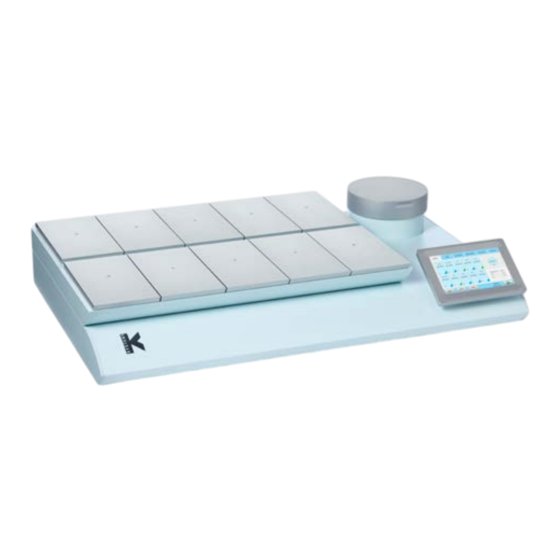
G210 InviCell
Long-Term Incubator
User Manual
Models: InviCell Standard and InviCell Plus with
SignipHy™pH Monitoring System
+45 46 79 02 02 | sales@coopersurgical.com | fertility.coopersurgical.com
CooperSurgical, Inc.
95 Corporate Drive, Trumbull, CT 06611, USA
2797
Only
Advertisement
Table of Contents

Related Manuals for K-Systems G210 InviCell


Summary of Contents for K-Systems G210 InviCell
- Page 1 CooperSurgical Fertility Company G210 InviCell Long-Term Incubator User Manual Models: InviCell Standard and InviCell Plus with SignipHy™pH Monitoring System +45 46 79 02 02 | sales@coopersurgical.com | fertility.coopersurgical.com CooperSurgical, Inc. 95 Corporate Drive, Trumbull, CT 06611, USA 2797 Only...
-
Page 3: Table Of Contents
Guidance and Manufacturer’s Declaration – Electromagnetic Emissions Guidance and Manufacturer’s Declaration – Electromagnetic Immunity Glossary of Safety and Information Symbols SECTION 4 - INSTALLATION Placement SECTION 5 - PRODUCT OVERVIEW Main Components IT Security Supplied Parts for G210 InviCell Standard... - Page 4 SECTION 6 - G210 INVICELL PLUS WITH SIGNIPHY™ PH MONITORING SYSTEM External Sensors, pH / CO Dish Insert for pH monitoring External Monitoring Supplied Accessories for G210 InviCell Plus with SignipHy pH Monitoring System SECTION 7 - SET-UP Gas Supply Factory Settings SECTION 8 - BASIC OPERATION...
- Page 5 Contents Create a New User Delete User Log Out Lost Password Alarm Errors SECTION 10 - K-LINK Starting K-Link Device Connection Measurement Section Alarm Display Section Graph Section Level Tab Pressure Tab Daily Average Tab Warning Tab Mail Tab Service Tab SECTION 11 - TROUBLESHOOTING Heating System Gas Regulator...
- Page 6 Contents Gas Calibration Procedure Chamber Lid Plug Verification of Gas Concentration in Chambers Temperature Calibration Temperature Calibration Procedure SECTION 13 - SERVICE Service plan On-screen Prompts Replacing the Origio Gas Line Filter Disposal of the Gas Line Filter SECTION 14 - DISPOSAL AND RECYCLING Environmental Protection for Disposal of the Product Recyclable Components SECTION 15 - WARRANTY INFORMATION AND LIMITS ON LIABILITY...
-
Page 7: Section 1 - Preface
G210 InviCell is designed to provide optimum conditions for gametes and embryos during long-term culture. For optimal use of the G210 InviCell, please read and follow the instructions in this User Manual. The incubator should be operated by trained personnel only. All sections of this manual should be read and understood fully before any operation of the incubator. -
Page 8: Section 2 - Introduction
The gas is constantly recirculated from the culture chambers through a HEPA (high-efficiency particulate air) / VOC (volatile organic compound) filter. The G210 InviCell Plus with SignipHy™ pH Monitoring System can be fitted with an accessory that monitors pH by surrogate media samples using a fluorescent marker contained in a disposable sample cup. -
Page 9: Intended User And Environment Of Use
Applicable Part Numbers K59500 G210 InviCell Standard Incubator K60000 G210 InviCell Plus with SignipHy pH Monitoring System SignipHy is an optional system that is not included as standard with G210 Invicell Plus and requires additional installation by CooperSurgical service personnel. -
Page 10: Significant Performance Characteristics
Section 2 Introduction Significant Performance Characteristics The incubator has been developed and optimised for gametes and embryos cultured with an overlay of either paraffin or mineral oil. Each chamber is designed to contain dishes from one patient only. Operation Principle The fertilised egg (zygote) is cultured for up to 6-7 days in a growth medium in the incubator with a controlled environment (temperature and CO ). -
Page 11: Dish Inserts
Section 2 Introduction Dish Inserts The chambers should only be fitted with special Dish Inserts (1), that allow safe placement of standard culture dishes (LifeGlobal, Falcon, Nunc, Vitrolife). Culture Chamber Each chamber is equipped with individual temperature sensors and heating control, to ensure a uniform heat distribution. -
Page 12: Section 3 - Safety Warnings
Use of other gases could result in serious injury, depending on the gas connected. WARNING: DO NOT disassemble or modify any part of the G210 Invicell, or substitute any component for any other. Doing so may result in damage to samples. -
Page 13: Cautions
Section 3 Safety Warnings Cautions CAUTION: Ensure the device is protected against power disruption by using a system, such as a Uninterruptible Power Supply, to provide emergency power if the mains power fails. CAUTION: Read and understand the manual completely before use. Keep the manual close to the unit. -
Page 14: Guidance And Manufacturer's Declaration - Electromagnetic Emissions
Section 3 Safety Warnings Guidance and Manufacturer’s Declaration – Electromagnetic Emissions The G210 is intended for use in the electromagnetic environment specified below. The customer or the user of the G210 should assure that it is used in such an environment. Emissions test Compliance Electromagnetic environment - guidance... -
Page 15: Guidance And Manufacturer's Declaration - Electromagnetic Immunity
Section 3 Safety Warnings Guidance and Manufacturer’s Declaration – Electromagnetic Immunity The G210 is intended for use in the electromagnetic environment specified below. The customer or the user of the G210 should assure that it is used in such an environment. IEC 61326-1 IMMUNITY Electromagnetic... - Page 16 Section 3 Safety Warnings IEC 61326-1 Compliance Electromagnetic environment - IMMUNITY Test Test level level guidance Power frequency 3 A/m 3 A/m Power frequency magnetic fields should be at levels characteristic of a typical (50/60 Hz) commercial environment. magnetic field IEC 61000-4-8 Portable and mobile RF communications equipment should be used no closer to...
- Page 17 Section 3 Safety Warnings NOTE 1 At 80 MHz and 800 MHz, the higher frequency range applies. NOTE 2 These guidelines may not apply in all situations. Electromagnetic propagation is affected by absorption and reflection from structures, objects and people. Field strengths from fixed transmitters, such as base stations for radio (cellular/cordless) telephones and land mobile radios, amateur radio, AM and FM radio broadcast and TV broadcast cannot be predicted theoretically with accuracy.
-
Page 18: Glossary Of Safety And Information Symbols
Section 3 Safety Warnings Glossary of Safety and Information Symbols Source: ISO 15223-1, BS EN 61010-1 and ISO 7000 Symbol Meaning Symbol Meaning In accordance with Annex II of the European Medical Device Directive 93/42/ Catalogue or Part number 2797 EEC, as amended by Directive 2007/47/EC Caution: US Federal law... - Page 19 Section 3 Safety Warnings Warranty label Importer GAS (MAX 1 BAR) Gas Inlets CO Fragile, handle with care Sample Port Sample Port...
-
Page 20: Section 4 - Installation
Incorrect installation could result in overall poor performance. The G210 InviCell is designed as a stationary unit and, therefore, not to be moved once it has been installed. If the incubator needs to be relocated, please contact Customer Service. -
Page 21: Section 5 - Product Overview
Product Overview SECTION 5 - PRODUCT OVERVIEW Main Components Components Incubator Chambers Touchscreen Preparation Chamber Origio Gas Line Filter Figure 5-1G210 InviCell Standard and Plus models - front view Figure 5-2 G210 InviCell Standard and Plus models - raised top section... -
Page 22: It Security
Section 5 Product Overview Components Product label Mains connection with fuse Ventilation holes Gas inlet connectors Alarm output Ethernet connector** **External computing devices connected to the Ethernet on the unit must only be Limited Power Source and SELV circuit according to the standard IEC 62368-1 IT Security The G210 does not require a connection to a network or to a computer to perform its normal function. -
Page 23: Supplied Parts For G210 Invicell Standard
Section 5 Product Overview On base of unit Figure 5-3 G210 InviCell Standard Model - back view (see page 20 for InviCell Plus) Supplied Parts for G210 InviCell Standard • 1 x Origio Gas Line Filter • 2 x HEPA Inline Filter for input gas supply •... -
Page 24: Optional Order Codes
59902-1 Lid Seal for Preparation Chamber 59688 Gas sampler coupling 11103 G100 Gas Analyser 11006 Solid Temperature Sensor (use with K-Systems F100 Thermometer) 59655 XLR6 Receptacle Connector 32903 G210 User Manual 60017 Connector for External CO sensor 18-25mm (Plus models only) -
Page 25: Specification Table
Section 5 Product Overview 1 packet of Chamber Lid plugs (10 pieces) 1 USB drive containing K-Link software Specification Table Criteria Specification Overall dimensions, (L x W x 855mm x 570mm x 180mm Weight 45kg Temperature range 35 – 42°C User interface Touchscreen Digital temperature readout, data logger, temperature setpoint,... -
Page 26: Section 6 - G210 Invicell Plus With Signiphy™ Ph Monitoring System
All external sensors are completely independent of the functions and controls in the G210 InviCell Plus with SignipHy pH monitoring as they are connected to and powered by instruments independent of the G210 InviCell Plus with SignipHy pH Monitoring System. -
Page 27: Dish Insert For Ph Monitoring
External Monitoring A separate guide is available with details. Contact Customer service for a copy of the guide, which should be given to installers of any independent monitoring system. Supplied Accessories for G210 InviCell Plus with SignipHy pH Monitoring System •... -
Page 28: Section 7 - Set-Up
Section 7 Set-up SECTION 7 - SET-UP Before use, see chapter “Section 9 - Settings”. Gas Supply 1. The G210 is not supplied sterile and should be cleaned before use. Make sure the gas input ports at the back of the incubator are also cleaned. See “Section 12 - Maintenance”... -
Page 29: Section 8 - Basic Operation
Section 8 Basic Operation SECTION 8 - BASIC OPERATION CAUTION: Do not use the incubator if the alarm system of the device has issued a failure message and the cause of the failure has not been corrected. It is important that the appropriate Dish Inserts are selected for the culture dishes used (LifeGlobal, Falcon, Nunc, Vitrolife) to ensure there is direct contact between the dish and the heated surface. -
Page 30: Main Menu
Section 8 Basic Operation Main Menu Setpoint Settings Log Menu Calibration Service Alarm Date and Advanced Time View Main Menu The main screen provides an overview of the temperature and gas concentrations inside the incubator. Advanced Menu 1. Press Advanced (1) in the main menu. -
Page 31: Chamber Information
Section 8 Basic Operation 2. The advanced menu shows the temperature in each chamber. 3. Chambers that are marked with blue (2) are occupied, chambers marked green (3) are vacant. 4. To return to the main menu press Basic (4). 5. -
Page 32: Log
Section 8 Basic Operation 1. The Log menu shows the temperature and gas concentration over a three hour period. 2. Press the Flow/Press button (1) to see gas flow and pressure (see below image) over a three hour period. 3. Press Level button (2) to return to temperature and gas concentration. -
Page 33: Changing The Temperature Setpoint
Section 8 Basic Operation 3. Enter the password and press OK (4). Changing the Temperature Setpoint 1. Adjust the temperature setpoint by pressing the arrow buttons. Press Save (1). Changing the Gas Setpoint 1. Adjust the gas setpoint by pressing the arrow buttons. -
Page 34: Section 9 - Settings
Section 9 Settings SECTION 9 - SETTINGS The Settings menu shows: 1. Time settings (1) 2. Date settings (2) 3. Time format (3) 4. Ethernet configuration (4) 5. Security settings (5) 6. System settings (6) 7. Language (7) 8. Basal Body Temperature (BBT) settings (8) To change some of these settings requires a login (see “Security Settings”... -
Page 35: Ethernet Settings
Section 9 Settings Ethernet Settings Select the Configure button from the settings menu. It is recommended to allocate a static IP address to the device. Consult an IT Specialist/Department for network settings. 1. Select DHCP (1), or 2. Static IP (2) 3. -
Page 36: Security Settings
Section 9 Settings 4. When BBT is activated the temperature in the setpoint menu cannot be changed. 5. Press one of the four time buttons (A, B, C or D). Adjust the time value by pressing the up and down arrows (5). 6. -
Page 37: Access Levels
Section 9 Settings Access Levels The unit supports three access levels: User, Administrator and Advanced User. Their characteristics are shown below: Advanced User Administrator (login User (login required) required) Changes that do not require login Change setpoint ... -
Page 38: Edit User
Section 9 Settings Edit User 1. Select a user in the Security window, and press Edit (1) . 2. The access level, name and password can be edited here. Press Save (2) when done. Change Password 1. Press Change password (1) to change the admin password. -
Page 39: Create A New User
Section 9 Settings Create a New User 1. In the security window, press New (1). Delete User 1. Select a user in the security window, and press Delete (1). 2. It is not possible to delete the “admin” user. 3. Confirm ‘OK’ to delete a user. Log Out 1. -
Page 40: Alarm
Section 9 Settings Alarm A flashing red light alarm button indicates that an alarm has been activated. An audible alarm will also be activated. Press the alarm button to open the alarm message box. The alarm box shows information about the current alarm. -
Page 41: Section 10 - K-Link
Section 10 K-Link SECTION 10 - K-LINK K-Link software can be used to communicate with a G210 over a TCP/IP network to retrieve, display and save a log of measurements, warnings, and daily averages into a spreadsheet. K-Link can also be configured to send email notifications when alarms are triggered. Starting K-Link To launch the K-Link software, double click on the K-Link icon on the desktop or in the... -
Page 42: Measurement Section
Section 10 K-Link NOTE: Ensure that the system time of the computer running the K-Link software and the system time of the G210 have both been set to the correct time before proceeding. NOTE: To ensure a stable connection between K-Link and the G210, it is recommended that the G210 be configured with a static IP address. -
Page 43: Graph Section
Section 10 K-Link Graph Section The graphs displayed will automatically scale to fit the measurements however the Y-Axis can be adjusted by holding down the left mouse button and “dragging” a box around an area of interest then releasing the button. A single left-click anywhere on the graph will reset to the original scale. -
Page 44: Pressure Tab
Section 10 K-Link Pressure Tab The Pressure tab displays a graph of the device measurements over time. Daily Average Tab The Daily Average tab displays daily averages for the individual measurements collected from the device every 24 hours. -
Page 45: Warning Tab
Section 10 K-Link Warning Tab The Warning tab displays information about the last 50 individual alarms. Mail Tab The Mail tab allows users to configure K-Link to email notifications about alarms and service information. Note: It is recommended to configure K-Link to a specified mail server. Consult your IT Department for mail server information. -
Page 46: Service Tab
Section 10 K-Link Service Tab The service tab presents software versioning information, device connectivity and serial number information. It also shows counters to indicate when a general service check, a filter change should be conducted. When the counters time out, the service alarm light is triggered and will remain active until all counters are reset. -
Page 47: Section 11 - Troubleshooting
Section 11 Troubleshooting SECTION 11 - TROUBLESHOOTING Heating System Symptom Cause Action The temperature has not Wrong temperature and the Ensure all lids are closed and wait for stabilised within 0.5°C of the alarm is on the temperature to stabilise. setpoint. -
Page 48: Gas Consumption
Section 11 Troubleshooting Symptom Cause Action Lid(s) are left open Close lid(s) Poor O Seals are damaged or missing on regulation Check the seals are intact lid(s) Concentration gas concentration more than Allow system to stabilise by closing all alarm ±1% from setpoint lids Check N... -
Page 49: Section 12 - Maintenance
Section 12 Maintenance SECTION 12 - MAINTENANCE Periodic cleaning is recommended as part of routine maintenance. Disinfection is also recommended for media spills, visual accumulation of dust, and other evidence of contamination. Clean and disinfect the G210 and, when necessary, sterilise the Dish Inserts immediately after any media spills. -
Page 50: Sterilising The Dish Inserts
Validation Check Perform the following validation gas and temperature checks after all cleaning, disinfecting and sterilising or at least every two weeks to ensure the G210 InviCell is operating correctly. Gas Calibration It is very important that the G210 is not emptied of gas during the gas calibration procedure. -
Page 51: Gas Calibration Procedure
Section 12 Maintenance Ensure the gas analyser is prepared as per the gas analyser user manual. Gas flow to the Preparation Chamber should be switched off during gas calibration. (See page 29, Changing the Gas Control Settings). Gas Calibration Procedure 1. -
Page 52: Chamber Lid Plug
Section 12 Maintenance Chamber Lid Plug A silicone plug is placed in the lid of each chamber. For collecting a gas sample, penetrate the lid plug with a needle attached to tubing and connect to the gas analyser input. Do not use needles larger than 0.5mm x 25mm. -
Page 53: Temperature Calibration
CSI recommends the F100 Precision Thermometer together with the Solid Temperature Sensor for temperature calibration. If the calibration is not performed with the K-Systems Solid Temperature Sensor, CooperSurgical cannot guarantee correct calibration of the device. -
Page 54: Section 13 - Service
Service SECTION 13 - SERVICE WARNING: DO NOT disassemble or modify any part of the G210 InviCell. For the reliable and safe operation of this incubator it is strongly recommended that inspections and services are performed as stated in the Service Plan below. Failing to follow this plan may cause the unit to stop performing as intended and cause damage to embryos, blastocysts etc. -
Page 55: Replacing The Origio Gas Line Filter
Section 13 Service Replacing the Origio Gas Line Filter Remove all samples from the chambers before replacing the filters. 1. To access to the filter compartment, push the safety lock lever (1) and lift the upper part of the incubator containing the chambers. -
Page 56: Section 14 - Disposal And Recycling
Section 14 Disposal and Recycling SECTION 14 - DISPOSAL AND RECYCLING Information on recycling and handling of the unit as per the WEEE Directive (Waste Electrical and Electronic Equipment). CAUTION: Contamination Hazard As this device may have been used for processing and treating infectious substances, it might be contaminated. -
Page 57: Section 15 - Warranty Information And Limits On Liability
Section 15 Warranty and Limits on Liability SECTION 15 - WARRANTY INFORMATION AND LIMITS ON LIABILITY Please refer to our Terms and Conditions on our website https://fertility.coopersurgical.com/ commercial-terms-and-conditions/... -
Page 58: Section 16 - Returning Product For Repair
Section 16 Returning Product for Repair SECTION 16 - RETURNING PRODUCT FOR REPAIR Please refer to the ‘Troubleshooting’ section in this manual before returning product. If you continue to have a problem with your device, please follow these instructions: Returned Goods Policy Goods will be accepted for return for the following reasons: •... -
Page 59: Customer Service Contact Details
Section 16 Returning Product for Repair Customer Service Contact Details Tel: +45 46 79 02 02 Fax: +45 46 79 03 02 E-mail: sales@coopersurgical.com fertility.coopersurgical.com Contact Details for Customers in the USA Tel: 800-243-2974 Fax: 800-262-0105 fertility.coopersurgical.com Obligation to Inform Any serious incident that has occurred in relating to this device should be reported to CooperSurgical via phone number +1 203-601-5200 Ext 3100 or by email at ProductSurveillance@coopersurgical.com and to the local Health Authority in your country.
Need help?
Do you have a question about the G210 InviCell and is the answer not in the manual?
Questions and answers