
Subscribe to Our Youtube Channel
Related Manuals for K-Systems G210 InviCell


Summary of Contents for K-Systems G210 InviCell
-
Page 1: User Manual
User Manual G210 InviCell Incubator Models: InviCell Standard and InviCell Plus Document K32903 | Issue: 9 | Date: June 4, 2018 | DRF: 4602 0086... -
Page 2: Table Of Contents
Supplied Accessories for G210 InviCell Standard Accessory Order Codes Specification Table Section 6 - G210 InviCell Plus External Sensors, pH / CO Dish Insert for pH Online External Temperature Additionally Supplied Accessories for G210 InviCell Plus Section 7 - Set-up Gas Supply Factory Settings... - Page 3 Contents Section 8 - Basic Operation Touchscreen Menu Main Menu Advanced Menu Chamber Information Edit Chamber Information Setpoint Changing the Temperature Setpoint Changing the Gas Setpoint Section 9 - Settings Changing the Date and Time Ethernet Settings Changing the Preparation Chamber Settings Changing Language Changing Basal Body Temperature Security Settings...
- Page 4 Contents Daily Average Tab Warning Tab Mail Tab Service Tab Section 11 - Troubleshooting Heating System Gas Regulator Gas Regulator Gas Consumption Touchscreen Section 12 - Maintenance Periodic Cleaning Disinfection Sterilizing the Dish Inserts Validation Check Gas Calibration Gas Sample Port Chamber Lid Plug Temperature Calibration Alarm Function Test...
-
Page 5: Section 1 - Preface
Preface Section 1 - Preface Thank you for choosing a K-Systems product. We hope you will be happy with your G210 InviCell. At CooperSurgical, we strive to provide the very best products and solutions for human IVF and the G210 InviCell is designed to provide optimum conditions for your embryos during long-term culture. -
Page 6: Section 2 - Safety
Use of other gases could result in serious injury, depending on the gas connected. DO NOT disassemble or modify any part of the G210 Invicell, or substitute any component for any other. Doing so may result in damage to samples. This voids the warranty and/or service contract. - Page 7 Always keep the red cap on unused gas inlets at the back of the unit and the protection cap on the sample port placed behind the Preparation Chamber. • Never use the unit without an original K-Systems K-730 filter. • DO NOT expose the filter to liquids. Change filters that have been exposed to liquids.
-
Page 8: Symbols
Safety Symbols Symbol Meaning WARNING: Indicates a potentially hazardous situation which, if not avoided, could result in death or serious injury. CAUTION: Indicates a potentially hazardous situation which, if not avoided, may result in minor or moderate injury. It may also be used to alert against unsafe practices. - Page 9 Safety Symbol Meaning This equipment must be protectively earthed Warranty label Ethernet Sample Port Sample port GAS (MAX 1 BAR) Gas Inlets CO Static sensitive (ESD) Fuse In accordance with Annex II of the European Medical Device Directive 93/42/EEC, as amended by Directive 2007/47/EC. 0086 EC REP Authorized Representative in the European Community...
-
Page 10: Section 3 - Installation
Incorrect installation could result in overall poor performance. The G210 InviCell is designed as a stationary unit and, therefore, not to be moved once it has been installed. If the incubator needs to be relocated, please contact technical support. -
Page 11: Section 4 - Intended Use
Applicable indications for use are subject to the regulations of the country into which the device is sold and also the availability of the G210 InviCell for clinical use is dependent on the regulatory approval status of the incubator within that country. -
Page 12: Dish Inserts
Dish Inserts. Chamber Heating Each chamber is heated with K-Systems unique non-inductive EM Neutra™ heating system, which provides a uniform heat distribution and ensures there is no electro-magnetic field around the embryos/ gametes. All chambers have their own individual sensors to ensure stable temperatures at all times and unidirectional gas flow across the chambers ensures even gas distribution in each chamber. -
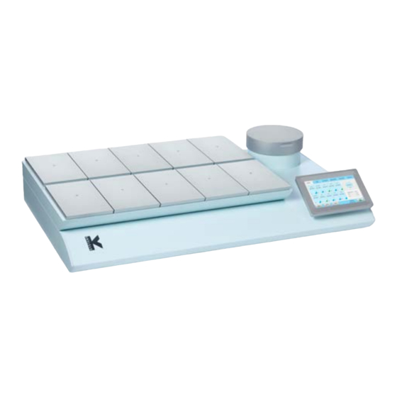
Page 13: Section 5 - Product Overview
Product Overview Section 5 - Product Overview Main Components Components Incubator Chambers Touchscreen Preparation Chamber K-730 Filter G210 InviCell Standard and Plus models - front view G210 InviCell Standard and Plus models - raised top section... -
Page 14: Supplied Accessories For G210 Invicell Standard
**External computing devices connected to the Ethernet on the unit must only be Limited Power Source and SELV circuit according to the standards IEC/UL 60950-1. G210 InviCell Standard Model - back view (see page 17 for InviCell Plus) On base... -
Page 15: Accessory Order Codes
59902-1 Lid Seal for Preparation Chamber 59688 Gas sampler coupling 11103 G100 Gas Analyzer 11006 Solid Temperature Sensor (use with K-Systems F100 Thermometer) 59655 XLR6 Receptacle Connector 32903 User Manual 60017 Connector for External CO sensor MTG (Plus models only) -
Page 16: Specification Table
Product Overview Specification Table Criteria Specification Overall dimensions, (L x W x H) 860mm x 550mm x 180mm Weight 53kg maximum Temperature range 35 – 42°C User interface Touchscreen Digital temperature readout, data logger, temperature User interface functions setpoint, calibration, warning for next service Connections Mains, CO gas, N... -
Page 17: Section 6 - G210 Invicell Plus
All external sensors are completely independent of the functions and controls in the G210 InviCell Plus as they are connected to and powered by instruments independent of the G210 InviCell Plus. CAUTION: Installations of external sensors must be performed by CooperSurgical or by persons authorized by CooperSurgical only. ... -
Page 18: Dish Insert For Ph Online
25 Pin D-Sub male connector prepared for soldering • 24 VDC power supply Further information is available in the Installation Guide for the G210 InviCell Plus. Additionally Supplied Accessories for G210 InviCell Plus • Connector for GMP251 Carbon Dioxide Probe from Vaisala Oyj •... -
Page 19: Section 7 - Set-Up
Set-up Section 7 - Set-up Before use, see chapter “Section 9 - Settings”. Gas Supply The G210 is not supplied sterile and should be cleaned before use. Make sure the gas input and output ports at the back of the incubator are also cleaned. See “Section 12 - Maintenance”... -
Page 20: Section 8 - Basic Operation
Basic Operation Section 8 - Basic Operation CAUTION: Do not use the incubator if the alarm system of the device has issued a failure message and the cause of the failure has not been corrected. It is important that the appropriate Dish Inserts are selected for the culture dishes used (Falcon, Nunc, Vitrolife) to ensure there is direct contact between the dish and the heated surface. -
Page 21: Main Menu
Basic Operation Main Menu Setpoint Settings Log Menu Calibration Service Alarm Advanced Date and View Time Main Menu The main screen provides an overview of the temperature and gas concentrations inside the incubator. Advanced Menu Press Advanced (1) in the main menu. -
Page 22: Chamber Information
Basic Operation The advanced menu shows the temperature in each chamber. Chambers that are marked with blue (2) are occupied, chambers marked green (3) are vacant. To return to the main menu press Basic (4). Patient ID (5). Chamber Information Press a chamber to get information about its status. -
Page 23: Log
Basic Operation The Log tab shows the temperature and gas concentration over a three hour period. Press the Flow/Press button (1) to see gas flow and pressure (see below image) over a three hour period. Press Level button (2) to return to temperature and gas concentration. -
Page 24: Changing The Temperature Setpoint
Basic Operation Enter your password and press OK (4). Changing the Temperature Setpoint Adjust the temperature setpoint by pressing the arrow buttons. Press Save (1). Changing the Gas Setpoint Adjust the gas setpoint by pressing the arrow buttons. Press Save (1) . It is recommended that gas concentrations are checked after changing the gas setpoint. -
Page 25: Section 9 - Settings
Settings Section 9 - Settings The Settings menu shows: Time settings (1) Date settings (2) Time format (3) Ethernet configuration (4) Security settings (5) System settings (6) Language (7) Basal Body Temperature (BBT) settings (8) To change some of these settings requires a login (see “Security Settings”... -
Page 26: Ethernet Settings
Settings Ethernet Settings Select the Configure button from the settings menu. We recommend allocating a static IP address to the device. However, you will need to consult with your IT department for network settings. Select DHCP (1), or Static IP (2) If static IP is selected, enter the settings provided by your IT department. -
Page 27: Security Settings
Settings When BBT is activated the temperature in the setpoint menu cannot be changed. Press one of the four time buttons (A, B, C or D). Adjust the time value by pressing the up and down arrows (5). Adjust all four time values (3). Press Save (6). -
Page 28: Access Levels
Settings Access Levels The unit supports three access levels: User, Administrator and Advanced User. Their characteristics are shown below: Advanced User Administrator User (login required) (login required) Changes that do not require login Change setpoint Change settings ... -
Page 29: Edit User
Settings Edit User Select a user in the Security window, and press Edit (1) . The access level, name and password can be edited here. Press Save (2) when done. Change Password Press Change password (1) to change the admin password. Enter the current password (2). -
Page 30: Create A New User
Settings Create a New User In the security window, press New (1). Delete User Select a user in the security window, and press Delete (1). It is not possible to delete the “admin” user. Confirm ‘OK’ to delete a user. Log Out In the Security window press Logout (1). -
Page 31: Alarm
Settings Alarm A flashing red light alarm button indicates that an alarm has been activated. An audible alarm will also be activated. Press the alarm button to open the alarm message box. The alarm box shows information about the current alarm. Press Mute (1) to turn off the audible alarm. -
Page 32: Section 10 - K-Link
K-Link Section 10 - K-Link K-Link software can be used to communicate with a G210 over a TCP/IP network to retrieve, display and save a log of measurements, warnings, and daily averages into a spreadsheet. K-Link can also be configured to send email notifications when alarms are triggered. Starting K-Link To launch the K-Link software, double click on the K-Link icon on the desktop or in the start menu. -
Page 33: Measurement Section
K-Link WARNING: Ensure that the system time of the computer running the K-Link software and the system time of the G210 have both been set to the correct time before proceeding. NOTE: To ensure a stable connection between K-Link and the G210, it is recommended that the G210 be configured with a static IP address. -
Page 34: Graph Section
K-Link Graph Section The graphs displayed will automatically scale to fit the measurements however the Y-Axis can be adjusted by holding down the left mouse button and “dragging” a box around an area of interest then releasing the button. A single left-click anywhere on the graph will reset to the original scale. Level Tab The Level tab displays a graph of the gas concentration levels over time. -
Page 35: Pressure Tab
K-Link Pressure Tab The Pressure tab displays a graph of the device measurements over time. Daily Average Tab The Daily Average tab displays daily averages for the individual measurements collected from the device every 24 hours. -
Page 36: Warning Tab
K-Link Warning Tab The Warning tab displays information about the last 50 individual alarms. Mail Tab The Mail tab allows users to configure K-Link to email notifications about alarms and service information. NOTE: It is recommended to configure K-Link to use your own mail server. Consult your IT Department for your mail server information. -
Page 37: Service Tab
K-Link Service Tab The service tab presents software versioning information, device connectivity and serial number information. It also shows counters to indicate when a general service check, a filter change or a UV light change should be conducted. When the counters time out, the service alarm light is triggered and will remain active until all counters are reset. -
Page 38: Section 11 - Troubleshooting
Troubleshooting Section 11 - Troubleshooting Heating System Symptom Cause Action The temperature is more than Wrong temperature The alarm is on 0.5°C off from the setpoint, wait for the temperature to stabilize Wrong temperature on The setpoint for temperature Check the desired temperature touchscreen after system has is wrong setpoint... -
Page 39: Gas Regulator
Troubleshooting Gas Regulator Symptom Cause Action System not powered on Check mains and main fuse gas regulator is off Activate O gas regulator No N or wrong gas type Check gas supply; make sure that Wrong O level measured at attached to N gas input 0.5-1.0 bar of N... -
Page 40: Section 12 - Maintenance
Complete validation check. Disinfection Disinfect the G210 InviCell in cases of contamination and/or spillage. Cleaning should precede disinfection. Promptly soak up excess liquid using a sterile cloth. Wipe all internal surfaces of chambers and lids with sterile wipes moistened with a disinfection solution containing 0.12% of active chlorine. -
Page 41: Validation Check
Validation Check Perform the following validation gas and temperature checks after all cleaning, disinfecting and sterilizing or at least every two weeks to ensure the G210 InviCell is operating correctly. Gas Calibration It is VERY important that the G210 is not emptied of gas during the calibration procedure. To do so will cause very unstable gas levels and gas flow, and will result in a considerable time before the gas concentration is recovered and becomes reliable and stable again. -
Page 42: Gas Sample Port
Maintenance Gas Sample Port The Gas Sample Port is located behind the Preparation Chamber. The Gas Sample Port is connected directly to the gas-mixing chamber. Connect a short length of tubing to the gas analyzer input. Connect the enclosed coupling to the other end of the tubing. Remove the protection cap from the sample port. - Page 43 Maintenance Coupling By following this protocol, the sampled gas re-enters the gas flow connected to as subsequent samples are collected from the next chamber. If output gas is not circulated, wait 3 minutes between sampling. Needle Verification of Gas Concentration in Chambers connected Connect a short length of tubing to the gas analyzer to inlet...
-
Page 44: Temperature Calibration
We recommend the F100 Precision Thermometer together with the Solid Temperature Sensor for temperature calibration. If the calibration is not performed with the K-Systems solid temperature sensor, CooperSurgical cannot guarantee correct calibration of the device. -
Page 45: Section 13 - Service
Service Section 13 - Service WARNING: DO NOT disassemble or modify any part of the G210 InviCell For the reliable and safe operation of this incubator it is strongly recommended that inspections and services are performed as stated in the Service Plan below. Failing to follow this plan may cause the unit to stop performing as intended and cause damage to embryos, blastocysts etc kept inside the incubator. -
Page 46: Replacing The K-730 Filter
(5). Lower the upper part of the incubator. CAUTION: Do not use the unit without a genuine K-Systems K-730 Filter. CAUTION: Insert filter with the filter label facing up. If the filter is not placed correctly, it can cause excessive gas consumption. -
Page 47: Section 14 - Disposal And Recycling
Disposal and Recycling Section 14 - Disposal and Recycling Information on recycling and handling of the unit as per the WEEE Directive (Waste Electrical and Electronic Equipment). CAUTION: Contamination Hazard As this device may have been used for processing and treating infectious substances, it might be contaminated. -
Page 48: Section 15 - Warranty Information And Limits On Liability
Warranty Information and Limits on Liability Section 15 - Warranty Information and Limits on Liability CooperSurgical warrants that this item will be free from defects in materials and workmanship for one year from the date of initial purchase. If CooperSurgical determines that the product fails to conform to that warranty during the one-year warranty period, CooperSurgical will, as the sole remedy for that failure to conform, repair or replace the product, at CooperSurgical’s discretion, free of charge. -
Page 49: Returned Goods Policy
Warranty Information and Limits on Liability Returned Goods Policy Goods will be accepted for return for the following reasons: • If shipment was made without the customer’s authorization or order • If incorrect items were shipped • If defective items were shipped •...
Need help?
Do you have a question about the G210 InviCell and is the answer not in the manual?
Questions and answers