Distech Controls EC-BOS-9 Installation Manual
Hide thumbs
Also See for EC-BOS-9:
- User manual (50 pages) ,
- Quick start manual (6 pages) ,
- User manual (28 pages)
Table of Contents
Advertisement
Quick Links
EC-BOS-9
Mounting and Wiring Guide
Product Description
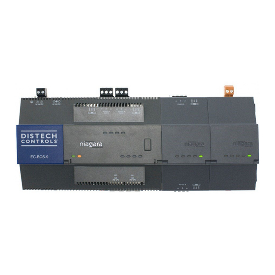
The EC-BOS-9 is a compact, embedded controller and server platform for connecting multiple and diverse devices and sub-systems. With Internet
connectivity and Webserving capability, the EC-BOS-9 provides integrated control, supervision, data logging, alarming, scheduling and network
management. It streams data and graphical displays to a standard Web browser via an Ethernet or wireless LAN, or remotely over the Internet. The
EC-BOS-9 operates with EC-Net™ web-based building management platform powered by the Niagara Framework®.
The integral power supply requires either 24Vac 50/60Hz, 24Vdc, or a wall-mount AC power adapter. Internal battery backup is not required or available.
DIN rail-mount option modules directly attach for additional communications ports, including for:
•
LonWorks (FTT-10)
•
RS232 (DB-9)
Dual RS485
•
The controller supports up to four (4) option modules. See
the RS485 connection to the controller. See
Included with the EC-BOS-9
The following items are also supplied with the controller.
MicroSD card in a plastic case
•
•
Two 3-position RS485 connector plugs
•
One 2-position power connector plug
•
Grounding wire
Option Module and Capacity
RS485
Wiring.
I n s t a l l a t i o n G u i d e
Considerations. Remote I/O expansion modules are supported by
Advertisement
Table of Contents

Subscribe to Our Youtube Channel
Related Manuals for Distech Controls EC-BOS-9


Summary of Contents for Distech Controls EC-BOS-9
- Page 1 Mounting and Wiring Guide Product Description The EC-BOS-9 is a compact, embedded controller and server platform for connecting multiple and diverse devices and sub-systems. With Internet connectivity and Webserving capability, the EC-BOS-9 provides integrated control, supervision, data logging, alarming, scheduling and network management.
-
Page 2: Material And Tools Required
Option Module and Capacity Considerations The EC-BOS-9 supports a maximum total of four option (expansion) modules in certain combinations. If you use two RS485 option modules, you are limited to one additional “non-RS485” module (LON or 232) for a total of three. The following figure shows some example combinations. -
Page 3: Safety Precautions
Remove all power to the EC-BOS-9 before attaching (plugging in) or detaching (unplugging) any option module, to prevent possible equipment damage. Removal of the EC-BOS-9 cover is not required. No configurable or user-serviceable items (such as jumpers or a battery) require cover •... -
Page 4: Environmental Requirements
Carefully slide the card shutter back over the card carrier opening until it clicks in place. When properly closed, the shutter should not protrude behind the mounting base. Mounting Mount the EC-BOS-9 in a location that allows clearance for wiring, servicing, and module removal. The following drawing shows the dimensions of an EC-BOS-9 with option modules. Figure 2: Mounting dimensions of the EC-BOS-9 and option modules. -
Page 5: Mounting On A Din Rail
EC-BOS-9. See Inserting or Removing the MicroSD Card. 1. Pull the EC-BOS-9 locking clip down. 2. Tilt the controller to hook it over the DIN rail. 3. Push down and in on the unit, fastening it to the rail. 4. Push the locking clip up to secure the controller. -
Page 6: Tab Mounting Dimensions
Mounting on a DIN Rail. Figure 3: EC-BOS-9 tab mounting dimensions EC-BOS-9. With no option modules added, allow at least 1.5" (38mm) clearance around all sides. Option expansion module. Up to four (4) may be used. See Option Module and Capacity Considerations. -
Page 7: Wiring And Power Up
5 Primary Ethernet port (Pri), 10/100/1000 Mbit, RJ–45 RS485 Wiring On the EC-BOS-9 top side, two RS485 ports operate as COM1 and COM2. Each port is capable of up to 115,200 baud, and uses a 3-position, screw terminal connector. 7/13... -
Page 8: Ethernet Wiring
• BIA - (Default, middle) Often best if the RS485 trunk needs biasing, but when the EC-BOS-9 is not installed at the end of the trunk. END - Often best if the EC-BOS-9 is installed at the end of an RS485 trunk of devices that is not already biased. -
Page 9: Earth Ground And Power
Power Up and Initial Checkout Enabling power starts a sequence of blinking LEDs. Also, the Niagara Framework logo on the cover illuminates whenever power is applied to the controller. Prerequiste: Ensure power and ground wiring to the EC-BOS-9 are ready—see wiring Earth Ground and Power. -
Page 10: Status Leds
BEAT (Heartbeat) LED For what to do next, refer to the EC-BOS-9 Install and Startup Guide, which explains how to commission a new EC-BOS-9 controller, that is, how to install the EC-Net 4 software, configure EC-Net platform settings, and install an EC-Net station: Initiating an EC-BOS-9 Shutdown When locally servicing an installed and configured (commissioned) unit, use this feature before removing power. -
Page 11: Stat (Status) Led
STAT (Status) LED The green STAT LED provides a CPU machine status check and should remain lit whenever the EC-BOS-9 is powered. If the status LED does not light while power is applied, contact System Engineering for technical support. -
Page 12: Pri, Sec (Ethernet) Leds
You can use a serial terminal program (for example: PuTTY) with the DEBUG port to access the controller’s system shell menu. This provides access to a few basic platform settings. Default DEBUG port settings are: 115200, 8, N, 1 (baud rate, data bits, parity, stop bits). For more details, refer to the EC-BOS-9 Install and Startup Guide. Login requires admin-level platform credentials. - Page 13 ©, Distech Controls Inc., 2024. All rights reserved. Images are simulated. While all efforts have been made to verify the accuracy of information in this manual, Distech Controls is not responsible for damages or claims arising from the use of this manual. Persons using this manual are assumed to be trained HVAC specialist / installers and are responsible for using the correct wiring procedures and maintaining safe working conditions with fail-safe environments.
Need help?
Do you have a question about the EC-BOS-9 and is the answer not in the manual?
Questions and answers