Table of Contents
Advertisement
Quick Links
ECB-VAV UUKL
Product Description
This document describes the hardware installation procedures for ECB-VAV UUKL Single Duct Variable Air Volume Controllers for smoke control.
The Distech Controls Variable Air Volume product line is designed to control and monitor various types of HVAC equipment such as baseboards, single
and multi-stage duct heaters, fans, valves, lights, etc. When connected to a Wireless Receiver, this product line can be used with a variety of wireless
battery-less sensors and switches.
Each controller uses the BACnet® MS/TP LAN communication protocol and is BTL®-Listed as BACnet Application Specific Controllers (B-ASC).
The ECB-VAV UUKL is the only VAV model to be used in the Distech Controls UUKL smoke control system. For detailed
requirements, specifications, and procedures for installing and operating UL 864 Listed equipment, you must refer to the Distech
Controls UUKL Smoke Control System Design Guide (UUKL Design Guide_UG_10_EN). Failure to meet the requirements or follow
the procedures in the Distech Controls UUKL Smoke Control System Design Guide can void the UL 864 Listing for smoke control
equipment.
General Installation Requirements
For proper installation and subsequent operation of the device, pay special attention to the following recommendations:
£
It is recommended that the controller(s) be kept at room temperature for at least 24 hours before installation to allow any condensation that may
have accumulated due to low temperature during shipping/storage to evaporate.
£
Upon unpacking, inspect the contents of the carton for shipping damages. Do not install a damaged device.
£
The device is designed to operate under environmental conditions that are specified in its datasheet.
£
Ensure proper ventilation of the device and avoid areas where corroding, deteriorating or explosive vapors, fumes or gases may be present.
£
Allow for proper clearance around the device's enclosure and wiring terminals to provide easy access for hardware configuration and maintenance.
£
When installing in an enclosure, select one that provides sufficient surface area to dissipate any heat generated by the device and by any other de-
vices installed in the enclosure. A metal enclosure is preferred. If necessary, provide active cooling for the enclosure.
£
The device's datasheet specifies the power consumption (amount of heat generated), the operating temperature range, and other environmental
conditions the device is designed to operate under.
£
Ensure that all equipment is installed according to local, regional, and national regulations.
£
Do not drop the device or subject it to physical shock.
£
If the device is used and/or installed in a manner not specified by Distech Controls, the functionality and the protection provided by the device may
be impaired.
Any type of modification to any Distech Controls product will void the product's warranty
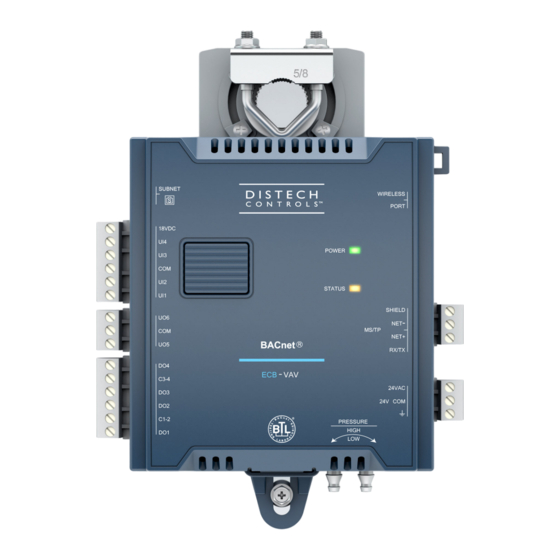
Figure 1:
ECB-VAV Controller
I n s t a l l a t i o n G u i d e
Advertisement
Table of Contents

Related Manuals for Distech Controls ECB-VAV UUKL


Summary of Contents for Distech Controls ECB-VAV UUKL
- Page 1 Do not drop the device or subject it to physical shock. £ If the device is used and/or installed in a manner not specified by Distech Controls, the functionality and the protection provided by the device may be impaired. Any type of modification to any Distech Controls product will void the product’s warranty...
-
Page 2: General Wiring Recommendations
(strip length: 0.25’’ (6 mm), tightening torque 0.5 Nm). £ Comply with all network and power supply guidelines outlined in the Network Guide. For the ECB-VAV UUKL controller, refer to the guidelines out- lined in the Distech Controls UUKL Smoke Control System Design Guide. - Page 3 Controller Dimensions & Components 5.51 [139.93] 2.75 [69.96] 3.70 [94.04] 2.27 [57.62] 2.27 [57.62] 1.25 [31.75] Damper Shaft 0.40 [10.05] Clamping Mechanism 0.86 [21.95] Opening for Damper Shaft 6.09 [154.76] Actuator Clutch for 7.90 [200.61] Manual Adjustment Front Profile ±0.20 [±...
-
Page 4: Mounting Instructions
Mounting Instructions Each controller is specially designed for easy installation either directly on an air duct or in a panel by using the integrated mounting collar and the screw that is provided with the controller. This mounting arrangement opposes the torque applied to the damper shaft. Mounting Position To prevent condensation on the VAV box’s damper shaft from entering the controller’s electronics, the controller’s mounting orientation should be any position above the damper shaft (between 0 and 180°) so that any condensation from the damper shaft will fall away from the controller’s electronics. - Page 5 VAV Controller Mounting Procedure Mount the controller as follows: 1. Configure the controller’s DIP switches. Refer to DIP Switch Identification and Configuration [pg. 3] for more information. 2. The VAV controller comes with the sliding grommet pre-installed. 3. Orient the controller into position on to the damper shaft so that wiring connections are easily accessible. The controller must be fitted onto the shaft such that the base of the controller is parallel to the VAV box (perpendicular to the damper shaft).
-
Page 6: Power Wiring
The Network Guide provides extensive information and requirements for powering a controller that uses a BACnet network for communications. It can be downloaded from our website. For the ECB-VAV UUKL controller, refer to the guidelines outlined in the Distech Controls UUKL Smoke Control System Design Guide It is recommended to wire only one controller per 24VAC transformer. -
Page 7: Daisy-Chain Wiring
Daisy-Chain Wiring Use an external fuse on the 24VAC side (secondary side) of the transformer, as shown below, to protect all controllers against power line spikes. Maintain consistent polarity when connecting controllers and devices to the transformer. One terminal on the secondary side of the transformer must be connected to the building’s ground. -
Page 8: Input Wiring
Input Wiring Input options must be properly configured in EC- gfx Program to ensure correct input readings. The table below shows the controller’s available universal input designation. For terminal block connector wiring best practices, see General Wiring Recommendations. Inputs can be connected as follows. Before connecting a sensor to the controller, refer to the installation guide of the equipment manufacturer. -
Page 9: Output Wiring
Output Wiring Output options must be properly configured in EC- gfx Program to ensure correct output values. For terminal block connector wiring best practices, see General Wiring Recommendations and Figure 2. Outputs can be connected as follows. Before connecting an output device (actuator, relay, etc.) to the controller, refer to the datasheet and installation guide of the equipment manufacturer. -
Page 10: Communications Wiring
For optimal performance, use Distech Controls 24 AWG (0.65 mm) stranded, twisted pair shielded cable or refer to the Network Guide for cable specification. For the ECB-VAV UUKL controller, refer to the guidelines outlined in the Distech Controls UUKL Smoke Control System Design Guide. The BACnet MS/TP communication wire is polarity sensitive and the only acceptable topology is to daisy-chain the cable from one controller to the next. -
Page 11: Device Addressing
For more information and detailed explanations on network topology and wire length restrictions, refer to the Network Guide, which can be downloaded from our website. For the ECB-VAV UUKL controller, refer to the guidelines outlined in the Distech Controls UUKL Smoke Control System Design Guide Device Addressing The Network Guide provides extensive information and requirements to implement a BACnet MS/TP network. - Page 12 Setting the Communicating Sensor Subnet ID ECB Series controllers can be commissioned with an Allure EC-Smart-Vue Series Communicating Sensor by connecting it to the controller as shown in the wiring diagram at the end of this guide. The default Subnet ID for an Allure EC-Smart-Vue Series Communicating Sensor is 1. To commission an ECB Series controller, the sensor’s Subnet ID must be set to 1.
- Page 13 Commissioning ECB-Series Controllers When using an Allure EC-Smart-Vue Series Communicating Sensor for commissioning ECB Series controllers (the DIP switch located on the faceplate is set to 0 (all off) and before code is downloaded to the controller EC-gfxProgram), connect the Allure EC-Smart-Vue Series Communicating Sensor to the controller with its Subnet ID set to 1.
-
Page 14: Setting The Baud Rate
Setting the BAUD Rate By default, the BAUD rate for the controller is set to automatically detect the current communication BAUD rate of the connected BACnet MS/TP network (AUTO). This is the preferred setting for a controller. However, at least one controller on the BACnet MS/TP network data bus must have its BAUD rate set. -
Page 15: Wireless Installation
Wireless Installation When connected to a Wireless Receiver, controllers can receive input signals from a wide selection of wireless devices. Compatible wireless devices in- clude temperature sensors, duct sensors, window/door contacts and light switches. These devices are easy to install, and can be mounted on a wide range of building materials. -
Page 16: Maintenance
Directive applies to standalone products, for example, products that can function entirely on their own and are not a part of another system or piece of equipment. For this reason, Distech Controls products are exempt from the WEEE Directive. Nevertheless, Distech Controls products are marked with the WEEE symbol , indicating devices are not to be thrown away in municipal waste. -
Page 17: Troubleshooting Guide
Distech Controls UUKL Smoke Control System Design Guide . Wire type Check that the wire type agrees with the specification of the Network Guide , or for the ECB-VAV UUKL controller, refer to the Distech Controls UUKL Smoke Control System Design Guide . - Page 18 ©, Distech Controls Inc., 2015-2019. All rights reserved. Images are simulated. While all efforts have been made to verify the accuracy of information in this manual, Distech Controls is not responsible for damages or claims arising from the use of this manual.
Need help?
Do you have a question about the ECB-VAV UUKL and is the answer not in the manual?
Questions and answers