Table of Contents
Advertisement
EC-BOS-8 UUKL
Mounting and Wiring Guide
Product Description
This document covers the mounting and wiring of the Distech Controls
EC-BOS-8 UUKL controller. For more detailed specifications regarding
the EC-BOS-8 UUKL, refer to the Distech Controls UUKL Smoke Control
Design Guide (UUKL Design Guide_UG_10_EN).
The EC-BOS-8 UUKL is a compact, embedded controller and server
platform for connecting multiple and diverse devices and sub-systems.
With Internet connectivity and Webserving capability, the EC-BOS-8
UUKL provides integrated control, supervision, data logging, alarming,
scheduling and network management. It streams data and rich graphical
displays to a standard Web browser via an Ethernet or wireless LAN, or
remotely over the Internet. The EC-BOS-8 UUKL operates with EC-Net
4 web-based building management platform powered by the Niagara
Framework®.
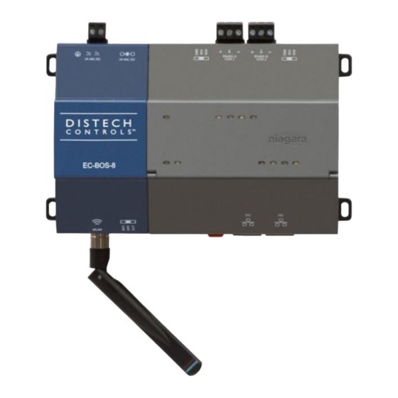
Figure 1:
EC-BOS-8 UUKL (with RS-485 UUKL module).
For more detailed specifications regarding the RS-485 UUKL module,
refer to the RS485 UUKL Installation Guide (RS485 UUKL_IG_10_EN)
and Distech Controls UUKL Smoke Control Design Guide (UUKL Design
Guide_UG_10_EN).
This document covers mounting and wiring of the following products.
Model
EC-BOS-8 UUKL
Multi-protocol web building controller
TM
The EC-BOS-8 UUKL is to be used in the Distech Controls'
UUKL smoke control system.
For detailed requirements, specifications, and procedures for
installing and operating UL 864 Listed equipment, you must
refer to the Distech Controls UUKL Smoke Control System
Design Guide (UUKL Design Guide_UG_10_EN).
Failure to meet the requirements or follow the procedures in
the Distech Controls UUKL Smoke Control System Design
Guide can void the UL 864 Listing for smoke control
equipment.
EC-Net 4 is required for any EC-BOS-8 UUKL. EC-Net
3.8.111 and higher also provides support of many EC-BOS-
8 UUKL features.
I n s t a l l a t i o n G u i d e
Description
AX
-
Advertisement
Table of Contents

Related Manuals for Distech Controls EC-BOS-8 UUKL


Summary of Contents for Distech Controls EC-BOS-8 UUKL
- Page 1 EC-BOS-8 UUKL controller. For more detailed specifications regarding refer to the RS485 UUKL Installation Guide (RS485 UUKL_IG_10_EN) the EC-BOS-8 UUKL, refer to the Distech Controls UUKL Smoke Control and Distech Controls UUKL Smoke Control Design Guide (UUKL Design Design Guide (UUKL Design Guide_UG_10_EN).
- Page 2 Option Module and Capacity access door or microSD card shutter. Considerations The EC-BOS-8 UUKL supports a maximum total of two RS485 option Static Discharge Precautions (expansion) modules in certain combinations. The microprocessors and associated circuitry within the EC-BOS-8 UUKL are sensitive to static discharge.
-
Page 3: Inserting Or Removing The Microsd Card
Caution). If the unit is currently running, see BOS-8 UUKL Shutdown,” on page 7. Note the EC-BOS-8 UUKL must also be unmounted from any DIN rail or screw tab mounting, as accessing the card uses space behind the mounting base. See Figure 3. -
Page 4: Mounting On Din Rail
2.2 (DC): Polarity is unimportant (uses onboard diode bridge), with neither leg tied to ground. • 2.3 (EC-BOS-8 UUKL Wall Plug Module) instead of wiring 24V to 2- position connector. 2. Tilt the EC-BOS-8 UUKL to hook over the DIN rail. -
Page 5: Ethernet Wiring
EC-BOS-8 UUKL is not installed at the end of the trunk. • END - Often best if the EC-BOS-8 UUKL is installed at the end of an RS485 trunk of devices that is not already biased. •... - Page 6 50%/50% on/off duty cycle. installation. During EC-BOS-8 UUKL bootup, this LED may blink at 1 Hz with a If USB media is detected, the system enters “restore mode”. In this 90%/10% on/off duty cycle, or in some other irregular pattern. When...
-
Page 7: Compliance And Approvals
24V power from the unit. In the case where the system cannot be put into a safe Behind the EC-BOS-8 UUKL front access door are two USB ports, two state, the “BACKUP” LED blinks in “error mode”: two quick pushbutton switches, and an associated LED. - Page 8 Canadian Department of Communications (DOC) interférences radio potentielles aux autres utilisateurs, le type d'antenne et son gain doivent être choisis afin que la puissance isotrope rayonnée This Device complies with Industry Canada License-exempt RSS équivalente (e.i.r.p.) ne soit pas plus que ce qui est nécessaire pour une standard(s).
-
Page 9: Tab Mounting Dimensions
Measurements shown below are in inches and (mm). Note that DIN mounting is recommended over tab mounting. See Rail” page 4. Figure 10: EC-BOS-8 UUKL tab mounting dimensions EC-BOS-8 UUKL. With no option modules added, allow at least 1.5" (38mm) clearance around all sides, and minimum 3" (76mm) at bottom for WiFi antenna. “Option Module and Capacity Option expansion module. - Page 10 ©, Distech Controls Inc., 2010 to 2019. All rights reserved. Images are simulated. While all efforts have been made to verify the accuracy of information in this manual, Distech Controls is not responsible for damages or claims arising from the use of this manual. Persons using this manual are assumed to be trained HVAC specialist / installers and are responsible for using the correct wiring procedures and maintaining safe working conditions with fail-safe environments.
Need help?
Do you have a question about the EC-BOS-8 UUKL and is the answer not in the manual?
Questions and answers