Table of Contents
Advertisement
Quick Links
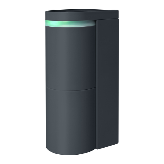
Vehicle Detection Sensor for Gate
Virtual Loop
Surface mount OVS-02GT
Feature
・ Detect the passage and presence of a vehicle with
a unique algorithm that uses microwaves (radio
waves).
・ Setting Adjustments Made with smartphone app.
・ Possible to share setting infomation
with others with using the app
・ Human Cancellation level is adjustable according
to the operation
・ Easy-to-see operation indicator
(Switchable On / Off)
・ Equipped with a heater for snow accretion
reduction (Changable power)
Installation Instructions
Table of Contents
1
2
2-1
2-2
3
3-1
3-2
3-3
4
5
6
6-1
Appications
6-2
6-3
6-4
6-5
6-6
6-7
6-8
7
7-1
7-2
7-3
7-4
8
8-1
8-2
8-3
8-3-1
8-3-2
8-3-3
8-3-4
8-3-5
8-3-6
8-3-7
8-3-8
8-3-9
8-4
8-4-1
8-4-2
8-4-3
8-4-4
8-4-5
8-4-6
8-5
9
10
10-1
Specifications
10-2
10-3
10-4
-1-
No.59-3045-2
P.2
P.3
P.3
P.4
P.4
P.5
P.6
P.7
P.8
P.8
P.9
P.10
P.10
P.11
P.12
P.13
P.14
P.15
P.18
P.19
P.21
P.23
P.24
P.25
P.25
P.26
P.26
P.26
P.27
P.28
P.28
P.28
P.29
P.30
P.30
P.31
P.31
P.32
P.33
P.34
P.35
P.37
P.37
P.38
P.38
Advertisement
Chapters
Table of Contents

Subscribe to Our Youtube Channel
Related Manuals for Optex Virtual Loop


Summary of Contents for Optex Virtual Loop
-
Page 1: Table Of Contents
No.59-3045-2 Installation Instructions Vehicle Detection Sensor for Gate Virtual Loop Surface mount OVS-02GT Table of Contents Safety precautions P.2 Before using the product Detection principle of the sensor P.3 Sensor operation P.3 Name of each parts Product model number Unit configuration... -
Page 2: Safety Precautions
Safety precautions This product is a vehicle detection sensor that detects the entry, presence, and departure of vehicles. Do not use it in any other purpose. For Safe Use About the Marks The description given here is for correct usage of the product without causing damage to you, other personnel as well as damage to properties.The marks and their meanings are as follows: Please read the text after understanding the contents well. -
Page 3: Before Using The Product
Before using the product Detection principle of the sensor • This sensor uses the reflection of microwave to detect vehicles. • The microwave sensor uses FMCW technology to detect the presence of a vehicle. Sensor operation Detection area Non-detection Detection When a vehicle enters the detection area, the sensor The sensor is a non-detection status when the will change to a detection status. -
Page 4: Name Of Each Parts
Name of each parts Product model number The product model number denotes the product configuration as follows. For details, see P37 "10-1 Specifications". OVS-02 Mount (Color) BL : Black GT ︓Surface mount Unit configuraion ●Surface Mount OVS-02GT Top screw Screw (for fix Top cover) Top cover Sensor unit Rotates 96°... -
Page 5: Sensor Unit (Common For All Models)
Sensor unit (Common for all models) Operation indicator can be selected to On / Off. (Refer P30 8-4-1 “Operation Indicator” ) Sensor unit Terminal block ●Operation indicator Operation mode Operation status Status Operation indicator Standby Solid Green Standby Enviromental notification Solid Purple Standard operation Pre-detection... -
Page 6: Settings (App)
Please allow use of these features. GooglePlay AppStore Donwload the smartphone App from the 2D code or search it with words “OPTEX Virtual Loop” at AppStore or GooglePlay. OPTEX VirtualLoop Log in to the App After starting the App for the first time and consenting to the terms and conditions, the screen to set an App user will appear. -
Page 7: Installation Steps
Installation steps Verify the sensor P.9 to 10 installation conditions Record the sensor name and installation layout Create an installation diagram and keep them in a safe place. Drilling holes in the installation area P.14 P.15 to 17 *Angle adjustments can be made Place the unit go to P.29 to 33 When using Input/Output,... -
Page 8: Preparation Before Operation
Preparation before operation Applications • Select the application that matches how the sensor is to be used. Do not use the product for purposes other than the selectable applications. Some models are not suitable for some applications. Barrier - Activation : Opening a barrier / actvating a gate system Barrier - Protection : For vehicle protection... -
Page 9: Sensor Installation Recommendations (For Barrier)
Sensor installation recommendations (for Barrier) Install the sensors with the layout shown below. When the installation direction or installation height is inappropriate, the sensor does not operate properly. - The sensor angles shown below are for vehicles enter parallel to the drive way. The sensor angle should match the angle of the vehicle (not the driveway). -
Page 10: Sensor Installation Recommendations (For Swing Gate)
Sensor installation recommendations (for Slide gate) Install the sensors with the layout shown below. When the installation direction or installation height is improper, the sensor will not operate properly. - The sensor angles shown below are for vehicles entering parallel to the drive way. The sensor angle should match the angle of the vehicle (not the drive way). -
Page 11: Sensor Installation Recommendations (Car Warning)
Sensor Installation Recommendations (for Car warning) When installing the sensor, install the pole so that the layout is as shown in the figure below. If the installation direction or height of the sensor is not correct, it will not operate properly. Installation height : The underside of the sensor is 500 mm from the ground ... -
Page 12: Installation Precautions For Specific Areas
Installation precautions for specific areas Tiltedf pole If the sensor is installed on a tilted pole, it will see the ground and not operate properly. Make sure to install Sensor detection area the sensor on a pole that is vertical to the ground. 地面... -
Page 13: Sensor Detection Conditions
Sensor detection conditions • Below are the conditions that vehicles must satisfy to be detected by the sensor. 3300–5000mm Vehicle length: 3300mm (130in.) or more, 1200–2100mm (130–197in.) (47–83in.) 5000mm (197in.) or less Vehicle width: 1400mm (55in.) or more, 2.5t (5512lb.) 1900mm (75in.) or less or less Vehicle height: 1200mm (47in.) or more,... -
Page 14: Installation Steps (Basic)
Installation steps (Basic) Preparation for installation ■ Required Tools ■ ●Small screwdriver, Phillips #1 ●Screwdriver, Phillips #2 • On a square pole or a wall, drill holes to install the unit as shown below. If tapped holes cannot be made, make pilot holes of ø4.3mm (0.17in.), and secure the unit using nuts. -
Page 15: Installation
Installation [1] Loosen the screws on the top and bottom covers, and remove the covers. * Do not loosen the screws completely. The screws may fall out. If a screw is lost, use an M3 × 6 Philips screw. The rubber lid is difficult Top cover to reattach if it is detached completely. - Page 16 [3] When running a wire from a pole, cut the terminal cover with nippers by referring to the wiring holes on page 14, and put wires through the sensor housing. Do not use a powered screwdriver when mounting the unit to a pole. ●...
- Page 17 [5] Install the sensor unit into the sensor housing. At this point, push excess wire out on the pole side. [6] Rotate the sensor unit to adjust its angle to meet the sensor installation condition (adjustable angle: 96° to left and right). Log in to the sensor with smartphone App [7] Verify the detection area according to “6-1.Applicatiions”...
-
Page 18: Calibration
Calibration Calibration function This function memorizes the background of the detection area when no pedestrians or vehicles are present. This function ensures the stability of vehicle detection by recording the environment. Perform calibration after every sensor installation. This process makes the sensors performance higher and more stable. How to perform calibration [1] Verify that there are no vehicles, pedestrians, work tools, or any other temporary objects which may be removed in the detection area. -
Page 19: Detection Area Check
Detection area check Detection area check This function allows you to virtually check the invisible detection area using indicators on the App or the operation indicator. It is possible to verify the correct angle and size of the detection area. During this process, the human cancellation function is disabled, and any moving objects can be detected. - Page 20 [1] Check inside the detection area Stand at the center of the vehicle lane (position [1] in the figure below) and walk in the direction of vehicle access. The position where the operation indicator changes from blinking green to blinking red (detection status) is the edge of the detection area. (In normal operation mode, the detection area may be a little bit longer.
-
Page 21: Check And Change Settings (How To Use The App)
Check and change settings (How to use the app) Icons Below are the icons used in the App. 2D code : This is used to log in to the sensor, or to share Favorites. Folder : This is used to read a 2D code that has been saved onto a smartphone. Save : This is used to save 2D codes and Favorites. - Page 22 Signal strength : This indicates the strength of signals transmitted between the sensor and the smartphone. If the signal strength is low, approach the sensor and perform setting. Menu : The items shown below are displayed. Save/Share setting : Current settings can be checked, saved and shared. Favorite : This is used to check Favorites and reflect them to the settings.
-
Page 23: App Description (Status Screen)
App description (Status screen) - Check and set the sensor status. ■ Applications Status Change it by selecting Menu Icon > Favorite > Select application. ● Detection status Application Barrier Protection 90 deg [1] Detection This indicates the detection status of the sensor. (Updated Detection status approximately once per second. -
Page 24: App Description (Parameter Screen)
App description (Parameter screen) - Check and change the sensor parameters. ■ Applications Parameter Change it by tapping Menu Icon > Favorites > Select application. [1] Detection range Application Barrier Protection 90 deg Refer to page 8 Detection range 3.5m (11.5’ ) [2] Main sensitivity Main sensitivity Lv.2... -
Page 25: Main Sensitivity
The following setting items should be configured if the sensor does not operate as expected during a system operation check or if an error occurs. These do not need to be set for normal installation. Change the settings as required using the App. Main sensitivity 8-3-1 This parameter adjusts the sensitivity of detection when a vehicle enters the detection area. -
Page 26: Close Range Sensitivity
Close range sensitivity 8-3-3 This parameter adjusts the sesitivity of close range 100-500mm (4-20 in.) from sensor when a vehicle enters the detection area. The vehicle detection capability (close range) and the false detection avoidance capability have the relationship shown in the figure below. Close range sensitivity 1... -
Page 27: Sensitivity Boost, Sensitivity Boost Timer
Sensitivity boost, Sensitivity boost timer 8-3-6 This can be used to avoid contact between vehicles that move backwards soon after passing under a barrier and the descending barrier arm. By enabling this function, sensitivity is increased for a set time period to detect backward-rolling vehicles more easily. -
Page 28: Relay Response Time
Relay response time 8-3-7 This parameter adjusts the recognition time of the sensor. The respose time and the false detection avoidance capability have the relation shown in the figure below. Also it effects for human cancellation capability. +100ms +200ms +300ms Relay response time False detection HIGH... -
Page 29: App Description (Input And Output Screen)
App description (Input and output screen) - Check and change the input / output settings of the sensor. ■ Applications Input and output Change it by selecting Menu Icon > Favorite > Select application. ● Indicator Application Barrier Protection 90 deg [1] Indicator Indicator Refer to page 30... -
Page 30: Operation Indicator
Operation indicator 8-4-1 The operation indicator can be selected to On or Off from the App. Set it from the “Indicator” item on the “Input and output” screen.The operation indicator is always On while connected to the App. ●Operation indicator On / Off function •... -
Page 31: Mode
Mode 8-4-3 Signals can be selected according to the application of the output signals. Refer to the section below and make a selection. Detailed settings can not be made for modes othe than “Detection” . Detection : A normal detection. (The output state reflects the setting of Output delay, Hold timer and others.) Pre-detection : Outputs a pre-detection and a normal detection both. -
Page 32: Delay / Hold Timer
Delay / Hold Timer 8-4-5 Delay / Hold timer is the time between the sensor status change and the relay output change. Setting the timer shorter makes the response time faster. Note that detection also needs a response time, which is the time for the sensor to recognize an object and make the detection, separately from the timer time. -
Page 33: Input
Input 8-4-6 By inputting signals from other devices, outputs linked to other devices can be made. Change contacts according to the connected devices. Connect signals lines from a startup sensor or controller to the input terminals. Application : Link (OR gate, AND gate) When operating a charging system, the reliability can be increased by using inputs from an external device. -
Page 34: App Description (Information Screen)
The site name that was set at the first log in is displayed. Previous log in 2021/07/22 ● Version information (Non-editable) Nickname OPlivia [5] Software Belongs OPTEX [6] Firmware Last update 2021/05/25 When contacting us, please check the version information OPliam Nickname Belongs OPTEX ●... -
Page 35: Troubleshooting
Troubleshooting Symptom Cause Action Power may not be supplied. Connect to a 12 to 24VAC/DC power supply. Operation indicator does not turn On. The supply voltage may not be correct. Connect to a 12 to 24VAC/DC power supply. The relay output wiring is incorrect. Wire the relay output correctly. - Page 36 Symptom Cause Action Main or close range sensitivity is too high. Reduce Main or Close range sensitivity. Relay response time is too short. Increase Relay response time. The sensor detects a pedestrian with large The sensor may not discriminate between baggage or a metal object passing through large objects and vehicles.
-
Page 37: Specifications
Specifications 10-1 Specifications Name Vehicle Detection Sensor (Surface mount) Model OVS-02GT Detection method Microwave ( FMCW) Frequency Microwave︓24GHz、BLE communication︓2.4GHz Response MIN 500ms Supply voltage 12 to 24VAC/DC Power consumption Heater enabled︓Up to 300mA、Heater disabled︓Up to 90mA( at 24V ) Non-voltage solid state relay output 30VDC 0.3A or less (resistance load) (N.O. / N.C.) Spec Non-voltage mechanical relay output 30VDC 1A or less (resistance load) (N.O. -
Page 38: Dimensions
10-3 Dimensions [Unit: mm (in.)] : Screw holes compatible 78 (3 5/64) 80 (3 5/32) with OVS-01 10-4 Options ●Vertical Angle Adjustment Plate (3 °) ● OVS-MP Mini post for OVS series (US only) OVS-MPB:Black OVS-MPY:Yellow OVS-MPBCURB:Black for curb OVS-MPYCURB:Yellow for curb Up to three can be stacked in use. - Page 39 EU / UKCA Hereby, OPTEX declares that the radio equipment type OVS-02GT is in compliance with RED 2014/53/EU and UK Radio Equipment Regulations 2017. The full text of the DoC and information is available at the following URL. EU : https://navi.optex.net/cert/ce/ UKCA : https://navi.optex.net/cert/uk/...
- Page 40 OPTEX (EUROPE) LTD (UK) Tel : +44(0)1628 631 000 | Email: marketing@optex-europe.com OPTEX Technologies B.V. (The Netherlands) Tel : +31(0)20 369 81 74 | Email: marketing@optex-europe.com OPTEX SECURITY SAS (France) Tel : +33(0)437 555 050 | Email: contact@optex-security.com OPTEX SECURITY Sp.zo.o.
Need help?
Do you have a question about the Virtual Loop and is the answer not in the manual?
Questions and answers