Table of Contents
Advertisement
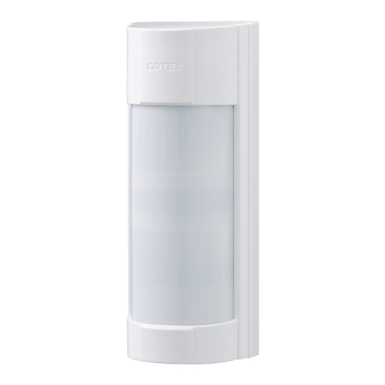
MULTI DIMENSIONAL OUTDOOR DETECTOR
MULTI DIMENSIONAL OUTDOOR DETECTOR
VX Infinity
VX Infinity
BATTERY OPERATED MODEL
VXI-R
Battery operated model with 2 PIR
VXI-RAM
VXI-R with anti-masking
VXI-RDAM
VXI-RAM with micro-wave
TM
The VX Infinity
report losses. The VX Infinity
outdoor environments.
FEATURES
BASIC FEATURES
- 12 m (40 ft.) by 90 degree flexible detection pattern adjustable to 5 ranges
- SMDA Logic for advanced temperature compensation and environmental noise immunity.
- Easy Masking for over spill prevention
- Double Conductive Shielding against bright light disturbance.
- Conduit/TX-Battery Case for both wired and wireless-ready models.
OPTIONAL FEATURES
- Active IR Anti-Masking for detecting covering objects
- Tough Mod Dual Technology based on OPTEX gold-plated microwave module
- Super Low Energy Circuit for maximum Battery life expectancy
CONTENTS
1
2
TM
series
series
TM
series provide highly reliable detection functions, reducing false reports or
TM
series deliver stable detection performance even in severe
INSTALLATION INSTRUCTIONS
3
2
4
3
5
4
6
4
4
7
5
7-1 SPECIFICATIONS
5
5
8
6
7
7
8
-1-
No.59-1936-1
9
11
12
13
13
14
14
15
Advertisement
Table of Contents

Related Manuals for Optex Infinity VX Series


Summary of Contents for Optex Infinity VX Series
-
Page 1: Table Of Contents
- Conduit/TX-Battery Case for both wired and wireless-ready models. OPTIONAL FEATURES - Active IR Anti-Masking for detecting covering objects - Tough Mod Dual Technology based on OPTEX gold-plated microwave module - Super Low Energy Circuit for maximum Battery life expectancy CONTENTS... -
Page 2: Introduction
INTRODUCTION 1-1 BEFORE INSTALLATION Failure to follow the instructions provided with this indication and improper handling may cause Warning death or serious injury. Failure to follow the instructions provided with this indication and improper handling may cause Caution injury and/or property damage. The check mark indicates recommendation. -
Page 3: Parts Identification
VXI-R -Precautions for installing two or more sensors VXI-RAM VXI-RDAM Do not install two or more VXI-RDAMs in side by side or face to face. Doing so may cause malfunction. VXI-RDAM may be installed in back to back. If mounting on the same wall, make sure that each unit is at least 1.0m (3.28 ft) apart from the other. -
Page 4: Detection Area
1-3 DETECTION AREA SIDE VIEW Length limiting position 1 (Default) Note>> The maximum detection length may vary as shown below due to environment conditions. Length limiting position 2 TOP VIEW Area diagram of horizontal position D Length limiting position 3 A B C E F G Length limiting position 4... -
Page 5: Transmitter Preparation
2-3 TRANSMITTER PREPARATION The transmitter used should have the internal dimensions of H 150 × W 34 × D 33 mm(H 5.91 × W 1.34 × D 1.30 inch) or H 112 × W 55 × D 35 mm.(H 4.41 × W 2.17 × D 1.38 inch) Unit: mm (inch) Connectors to be used Connector for POWER and ALARM... -
Page 6: Mounting
2-6 MOUNTING Mount the mounting plate. Mount the back box on the mounting plate. Put the top of the back Wall mount Pole mount box on the hook. Metal band * Use a metal band with 25 mm or less in width. Mount the transmitter on the back of the main unit. -
Page 7: Area Angle Adjustment
2-7 AREA ANGLE ADJUSTMENT Horizontal position D Horizontal position B (Default) (F: symmetrical position) A B C A B C E F G E F G A B C E F G Horizontal position C Horizontal position A (E: symmetrical (G: symmetrical position) position) -
Page 8: Detection Length Adjustment
2-9 DETECTION LENGTH ADJUSTMENT Adjust the PIR detection length by sliding the lower PIR to the desired position. IMPORTANT BOTH DETECTION AREAS MUST BE BLOCKED FOR DETECTION Both upper and lower detection area are blocked Detection! Only upper detection area is blocked Adjust the MW detection length by rotating the MW sensitivity adjustment according to the PIR area. -
Page 9: Switch Setting
SWITCH SETTING DIP switch PIR sensitivity selector 1 WALK TEST MODE 2 BATTERY SAVING TIMER 3 ALARM & TROUBLE OUTPUT 4 LED 5 ANTI-MASKING 6 MICROWAVE IMMUNITY MW sensitivity adjustment VXI-R -WALK TEST MODE VXI-RAM DIP switch 1 VXI-RDAM POSITION FUNCTION The LED lights irrespective of the DIP switch 4 (LED) setting. - Page 10 VXI-R -ALARM & TROUBLE OUTPUT VXI-RAM DIP switch 3 VXI-RDAM POSITION FUNCTION N.O. N.O. output N.C. N.C. output (Factory default) N.C. ⇔ N.O. VXI-R -LED VXI-RAM DIP switch 4 VXI-RDAM POSITION FUNCTION LED ON LED OFF Note>> (Factory default) If the LED lights, check the DIP switch 1 (WALK TEST MODE) setting.
-
Page 11: Walk Test
VXI-R -MICROWAVE IMMUNITY VXI-RAM DIP switch 6 VXI-RDAM POSITION FUNCTION MICROWAVE IMMUNITY logic is activated. Use this under IMMUNITY harsh environment (e.g. vegetation sway). MICROWAVE IMMUNITY logic is not activated. (Factory default) STD ⇔ IMMUNITY VXI-R -PIR SENSITIVITY VXI-RAM PIR SENSITIVITY SELECTOR VXI-RDAM HIGH POSITION... -
Page 12: Led Indication
LED INDICATION Blink Light YELLOW (VXI-RDAM only) <VXI-R> <VXI-RAM> Detector condition LED indicator Warm-up Note>> Blinks for approx. 60 seconds. The LED blinks even if the DIP switch 4 (LED) is set to “OFF”. Alarm Lights for 2 seconds. Masking detection (VXI-RAM only) Blinks 3 times and then repeats. -
Page 13: Battery
BATTERY The detector shares the battery with the transmitter. Check that the 2.5 – 10.0 VDC power battery is used for the transmitter. 6-1 HOW TO REPLACE BATTERY By following the procedures 1 and 2 in "2-4 BEFORE MOUNTING", remove the cover and then remove the main unit from the back box. -
Page 14: Specifications
SPECIFICATIONS 7-1 SPECIFICATIONS Model VXI-R VXI-RAM VXI-RDAM Detection method Passive infrared Passive infrared & Microwave PIR Coverage 12.0 m (40 ft) 90° wide / 16 zones PIR distance limit 12 – 2.5 m (5 levels) Detectable speed 0.3 – 1.5 m/s (0.98 – 4.92 ft/s) Sensitivity 2.0°C (3.6°F) at 0.6 m/s Power input... -
Page 15: Setting Of Special Detection Area
SETTING OF SPECIAL DETECTION AREA Using masking seals 2 to 6, you can set a special detection area for the horizontal position A or G. Set to the desired area setting direction When setting other than masking Select a masking seal from 2 to 6 (horizontal position A or G). - Page 16 (1) This device may not cause harmful interference. (2) This device must accept any interference received, including interference that may cause undesired operation. OPTEX CO., LTD. (JAPAN) OPTEX INCORPORATED (USA) OPTEX SECURITY Sp.z o.o. (POLAND) TEL:+1-909-993-5770 TEL:+48-22-598-06-55 (ISO 9001 Certified) Tech:(800)966-7839 URL:http://www.optex.com.pl/...
Need help?
Do you have a question about the Infinity VX Series and is the answer not in the manual?
Questions and answers