Saeco MAGIC M2 Technical Manual
Automatic machine for espresso coffee and hot beverages
Hide thumbs
Also See for MAGIC M2:
- Operation and maintenance manual (80 pages) ,
- Quick start manual (49 pages)

Related Manuals for Saeco MAGIC M2


Summary of Contents for Saeco MAGIC M2
- Page 1 Automatic machine for espresso coffee and hot beverages TECHNICAL MANUAL EN-GB ATTENTION: Read this user manual carefully before using the machine.
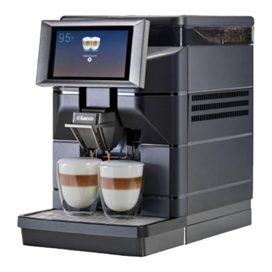
- Page 2 English MAIN PARTS MAIN PARTS VERSION M2 Tank lid with lock Coffee bean hopper lid Water tank lid Coffee bean hopper Water tank Brew group Touch Screen Control Panel Service door Mobile dispenser Cappuccinatore Suction tube for Cappuccinatore USB port Coffee grounds drawer Power button Cup holder grill...
- Page 3 English Air intake solenoid valve Compressor Air blowing solenoid valve Turbine Tablet Air discharge solenoid valve Rinse solenoid valve Solenoid pilot valve Hot water solenoid valve Steam boiler Discharge solenoid valve CPU card Steam solenoid valve Coffee boiler Service door microswitch Steam pump Microswitch coil and dosing unit door Coffee pump...
- Page 4 English MAIN PARTS VERSION M2+ Tank lid with lock Coffee bean hopper lid Water tank lid Coffee bean hopper Water tank Brew group Touch Screen Control Panel Service door Mobile dispenser Cappuccinatore Suction tube for Cappuccinatore USB port Coffee grounds drawer Power button Cup holder grill Chassis plug...
- Page 5 English Air intake solenoid valve Compressor Air blowing solenoid valve Turbine Tablet Water mains solenoid valve Rinse solenoid valve Air discharge solenoid valve Hot water solenoid valve Solenoid pilot valve Discharge solenoid valve Steam boiler Steam solenoid valve CPU card Service door microswitch Coffee boiler Microswitch coil and dosing unit door...
- Page 6 English MAIN PARTS VERSION B2 Tank lid with lock Coffee bean hopper lid Water tank lid Coffee bean hopper Water tank Brew group Touch Screen Control Panel Service door Mobile dispenser USB port Coffee grounds drawer Power button Cup holder grill Chassis plug Drip tray...
- Page 7 English Hot water solenoid valve Turbine Tablet Solenoid pilot valve Service door microswitch CPU card Microswitch coil and dosing unit door Coffee boiler Coffee grinder Coffee pump...
- Page 8 English MAIN PARTS VERSION B2+ Tank lid with lock Coffee bean hopper lid Water tank lid Coffee bean hopper Water tank Brew group Touch Screen Control Panel Service door Mobile dispenser USB port Coffee grounds drawer Power button Cup holder grill Chassis plug Drip tray Water connection coupling...
- Page 9 English Hot water solenoid valve Water mains solenoid valve Tablet Solenoid pilot valve Service door microswitch CPU card Microswitch coil and dosing unit door Coffee boiler Coffee grinder Coffee pump Turbine...
- Page 10 English MAIN PARTS VERSION M1 Water tank lid Coffee bean hopper lid Water tank Coffee bean hopper Touch Screen Control Panel Brew group Mobile dispenser Service door Suction tube for Cappuccinatore Cappuccinatore Coffee grounds drawer USB port Cup holder grill Power button Drip tray Chassis plug...
- Page 11 English Air intake solenoid valve Compressor Air blowing solenoid valve Turbine Tablet Air discharge solenoid valve Rinse solenoid valve Solenoid pilot valve Hot water solenoid valve Steam boiler Discharge solenoid valve CPU card Steam solenoid valve Coffee boiler Service door microswitch Steam pump Microswitch coil and dosing unit door Coffee pump...
- Page 12 English MAIN PARTS VERSION B1 Water tank lid Coffee bean hopper lid Water tank Coffee bean hopper Touch Screen Control Panel Brew group Mobile dispenser Service door Coffee grounds drawer USB port Cup holder grill Power button Drip tray Chassis plug...
- Page 13 English Hot water solenoid valve Turbine Tablet Solenoid pilot valve Service door microswitch CPU card Microswitch coil and dosing unit door Coffee boiler Coffee grinder Coffee pump...
- Page 14 English SAFETY INSTRUCTIONS Never allow water to come into Power cord contact with any of the electrical Never use power defective cords. parts of the machine: danger of short circuit! Hot water and steam Report any defects in the cord and/or plug may cause scalding! to the service provider immediately.
- Page 15 English Do not install the machine in a location Milk must kept cold, high where water jets may be used. temperatures will make it turn sour - this is a natural characteristic of milk. For this reason, the Cappuccinatore must be open flames and/or...
-
Page 16: Table Of Contents
English CONTENTS INTRODUCTION TO THE MANUAL........14.4 Mechanical unblocking of water mains inlet solenoid valve...... REMOVING COMPONENTS..........Preamble..................Icons Used..................15.1 Removing the External Cover.............. Documentation Required..............15.2 Removing the coffee grinder.............. Tools and Equipment Required............15.3 Rem. coff. grind................Safety Warning................ -
Page 17: Introduction To The Manual
This article is marketed under the responsibility of SaGa Coffee S.p.A. which Flat-head screwdriver 0.8 x 4 x 80 guarantees the product. Saeco is a registered trademark of Koninklijke Philips N.V. Allen wrench no. 5 and its use is licensed by Koninklijke Philips N.V. -
Page 18: Information About The Appliance
English INFORMATION ABOUT THE APPLIANCE Information for the Maintenance Technician Appliance Identification The appliance is identified by the model name and serial number shown on the The appliance must be installed in a well-lit, special plate. sheltered and dry place and on a table suitable to bear its weight. -
Page 19: Technical Data - Version M2 And B2
English Technical Data - version M2 and B2 Size (w x h x d) 280 x 470 x 481 mm Weight approx. 15 kg Machine housing material Thermoplastic material Power Rating See the data plate Supply Voltage See the data plate Power cord length approx. - Page 20 English Technical Data - version M2+ and B2+ Size (w x h x d) 280 x 470 x 481 mm Weight approx. 15 kg Machine housing material Thermoplastic material Power Rating See the data plate Supply Voltage See the data plate Power cord length approx.
-
Page 21: Technical Data - Version M1 And B1
English Technical Data - version M1 and B1 Size (w x h x d) 280 x 435 x 481 mm Weight approx. 12 kg Machine housing material Thermoplastic material Power Rating See the data plate Supply Voltage See the data plate Power cord length approx. -
Page 22: Safety
English SAFETY Preamble In case of failure or malfunctioning, please In compliance with the regulations and directives in force, SaGa Coffee has refer only to the qualified personnel of the established at its offices a technical pamphlet relative to the MAGIC appliance. technical service. -
Page 23: Handling And Storage
English HANDLING AND STORAGE All the operations described in this chapter must be performed exclusively by the service provider or a specialised technician, who shall organise all the operating steps and use only suitable means to ensure strict compliance with safety regulations in force. -
Page 24: Installation
English INSTALLATION The following illustration shows the required access distances: All the operations described in this chapter • to the keypad on the front of the appliance; must be performed exclusively by the • to the service units in the event of failure. service provider or a specialised technician, who shall organise all the operating steps and use only suitable means to ensure... -
Page 25: Connection And Setting For The Water Mains
English Key to access water tank and container of coffee beans: prevents access to the Group cleaning tablets: allow a correct cleaning of the brew group, increasing its water tank and the container of coffee beans by unauthorized personnel. (* only durability. - Page 26 English Before connecting the appliance to the Ensure that the hose is free of kinks and water mains, please read and follow the twists. applicable regulations in force in your country. Open the water knob. Remove the cap from the coupling on the appliance rear part. Two litres of water must be poured into the water tank for the first filling of the Connect the water network hose to the appliance's 3/4"...
-
Page 27: Connection To The Electric Network
English Enter the password of the technical profile. Select "Machine settings", then "Other Do not remove the water tank while the settings". Enable "Water main". machine is switched on. The machine does not recognise the presence of the tank, only the water level. In the case of operation using the water mains, the solenoid valve opens when the water level is below the minimum. -
Page 28: Description Of Controls
English DESCRIPTION OF CONTROLS Power button Operating in normal user mode It is located in the rear of the machine. If set to the "I" position the machine turns The layout and arrangement of the icons/screens in this manual is indicative only on (electrical functions enabled). - Page 29 English 6.3.2 Beverage selection area Select a beverage. The screen with the beverage customisations can be displayed. Whilst the beverage is being prepared, the beverage's preparation status is shown. alternatively it is possible to see the entertainment contents (e.g. a video). If enabled in menu, it is possible to stop a beverage's preparation.
-
Page 30: Supply And Start Up
English SUPPLY AND START UP Remove the coffee bean hopper lid. Opening the Upper Lid (* only versions M2, M2+, B2 and B2+). The upper protection cover should be removed in order to fill the containers. The cover is a safety device which allows access only to authorised personnel. Unlock the lid with the special key supplied to remove it. -
Page 31: Filling The Water Tank
English Filling the Water Tank Refit the protection cover as described in section "Closing the Upper Lid". (only versions M2, M2+, B2 and B2+). If the appliance is connected and set to the Measuring and Adjusting Water Hardness water mains, fill the water tank only to Measuring water hardness is very important in order to correctly manage the perform the descaling operation. -
Page 32: Closing The Upper Lid
English Select "Machine settings". Select "Maintenance". Select "Water filter settings". The anti-scale filter should be replaced Activate the water filter. Once the operation is finished fill the water again up the MAX level with fresh whenever indicated by the machine. drinking water. -
Page 33: Adjusting The "Aroma" - Amount Of Ground Coffee
English Remove the screw preventing accidental opening of the service compartment flap. The adjustment can be done using the lever located on the side in the service (* 120V USA version only). compartment of the machine. Remove the drip tray. Open the service compartment door and turn the lever by only one notch. -
Page 34: Adjusting The Beverage Dispenser
English 7.10 Adjusting the beverage dispenser Two cups can be placed under the dispensing spout to brew two cups of coffee at the same time. Most of the cups and mugs available on the market can be used with this coffee machine. -
Page 35: Washing The Parts Coming Into Contact With Food
English They have to be performed: 7.14 Washing the Parts coming into Contact with Food • at first start-up; Rinse all the parts coming into contact with food. • when the machine remains inactive for a long time (more than 2 weeks). •... -
Page 36: Programming Menu
English PROGRAMMING MENU Remove the screw preventing accidental opening of the service compartment flap. This chapter contains instructions on how (* 120V USA version only). Open the service compartment door. to set and change the programming parameters of the appliance. Therefore it is necessary to carefully read it and to understand the exact sequence of operations before performing them. -
Page 37: Enter Values
English Numeric keypad Favourites The favourites are links with the functions frequently used. After having added a function to the "favourites," simply view the "favourites" and tap the function for quick access. Tap the "favourites" icon to access the functions used frequently and stored as favourites. -
Page 38: Programming Menu
Events alert 9.1.3 Faults alert 4.3.1 Favourites list 4.3.2 Eliminate favourites Touchless Option 10.1 Saeco ProUp Machine Number and Name Installation date 10.1.1 Saeco ProUp Settings Contacts Information Energy Saving mode Energy Saving settings Energy Saving time frames Payment Systems... - Page 39 English 8.4.2 Items description of the programming menu OPTIO Description MENU ITEM N NO. Menu This menu makes it possible to access all the configuration parameters of the machine. Daily actions Groups together all of the functions that are used on a daily or more frequent basis (washes, resetting the residue counters, etc.) Washing/rinsing Automatic washing and rinsing functions of the appliance's functional units (Cappuccino maker).
- Page 40 English OPTIO Description MENU ITEM N NO. it means an incompatibility has been detected - Delete a recipe - Duplicate a recipe - Customise a recipe CREATING A NEW RECIPE The guided procedure allows a new recipe to be created. A screen is displayed where: - A name can be assigned to the new recipe - Tap...
- Page 41 English OPTIO Description MENU ITEM N NO. BASIC COFFEE PARAMETERS It is possible to set: - The name of the ingredient - The doses (water and powder) - Dispense a test beverage For appliances with a payment system, it is possible to set the change in the price of the selection. BASIC MILK PARAMETERS It is possible to set: - The name of the ingredient...
- Page 42 English OPTIO Description MENU ITEM N NO. 3.3.2 GUI package Allows a new template of the GUI package to be selected. 3.3.3 General settings of the Enables/disables the display of: display - The multimedia content available in normal user mode during dispensing. - The setting of the touchscreen's brightness;...
- Page 43 English OPTIO Description MENU ITEM N NO. 4.3.2 Eliminate favourites To remove a function from the "favourites" list, tap the function that you want to remove. To remove all the functions from the list of "favourites", tap "Delete all". Machine Number and Allows you to enter a numerical code and name that identifies the appliance.
- Page 44 English OPTIO Description MENU ITEM N NO. 6.1.2.1 Coin mechanism CREDIT PROGRAMMING (OVERPAY) It is possible to decide whether to: - Collect any credit in excess of the selection amount after a certain time expressed in seconds (parameter "deleted"). - Leave any credit in excess of the selection amount available for a subsequent selection (parameter "retained"). OVERPAY TIMEOUT Makes it possible to set the time when the credit will be released if a selection hasn't been made.
- Page 45 English OPTIO Description MENU ITEM N NO. 6.2.3 Beverages price The appliance (depending on the payment method) can manage up to 4 different prices for each selection. The prices can be active according to the time frame that has been set (standard or promotional). The prices are grouped into 4 lists.
- Page 46 English OPTIO Description MENU ITEM N NO. 8.1.10 Environment Variables Sets application environment variables. TECHNICAL FEATURES 8.2.1 Components test Allows the appliance's main components to be checked. The components that can be checked are displayed. Choose the component to be checked. BREWING UNIT Starts moving the brewing unit.
-
Page 47: Setting User Profiles Passwords
Mobile app which is the property of EVOCA. 10.1.1 Saeco ProUp From this page it is possible to enable the connection of the machine with Saeco Pro Up, display the associated ID and manage the certificate. Settings Setting user profiles passwords The use of some programming functions can be enabled/disabled via the access profiles. -
Page 48: Operation And Use
English OPERATION AND USE The use by children older than 8 years or by persons with reduced physical, mental or sensory abilities or with lack of experience and skills is allowed, provided that they are supervised or instructed on how to use the appliance correctly and that they understand the hazards involved. -
Page 49: Rinse/Self-Cleaning Cycle
English Rinse/Self-Cleaning Cycle Dispensing beverages coffee only The cycle permits the internal circuits to be rinsed with fresh water. The cycle is Insert the cup or glass under the dispenser. carried out: For the coffee circuit • When the machine is started; •... -
Page 50: Hot Water Dispensing
English Use cold (~5°C / 41°F) milk with a protein After a preset period of time following the content of at least 3% to ensure last beverage with milk dispensing, the top-quality beverages. Whole milk, machine automatically rinses the milk skimmed milk, soy milk or lactose-free milk circuit. -
Page 51: Emptying The Coffee Grounds Drawer And Drip Tray
- Select the dedicated manual. not dispense products. • Order and/or load the machine credits from the "Saeco Pro Up" app, if logged with registered and enabled user. • Make the adjustment of the technical setting directly from "Saeco Pro Up" app if After having inserted them the machine is ready to be used and the coffee logged with registered and enabled user. -
Page 52: Cleaning And Maintenance
English CLEANING AND MAINTENANCE 10.2.1 Maintenance Schedule Before performing any maintenance and/or cleaning operation, unplug the power Operation to be carried out Drip tray cord. Emptying and cleaning the coffee grounds drawer Cappuccinatore quick clean Thorough cleaning of Cappuccino The Manufacturer is not liable for damage maker with detergent Thorough cleaning of the Cappuccino or malfunctions caused by a wrong or lack... - Page 53 (*only versions M). Once a day thoroughly clean all the components of the cappuccino maker using the Saeco detergent. The Saeco detergent may be purchased at your local dealer or at authorised service centres. Failure to thoroughly clean the cappuccino maker with detergent can cause potentially harmful bacteria to spread.
- Page 54 English Confirm the process. The machine summarizes on the display all the phases to be Do not drink the solution dispensed during performed for the washing step-by-step. For example, the phases are the following: this procedure. The solution must be Fill the water tank.
- Page 55 English Remove the lower cover of the cappuccino maker. The steps below show how to remove and clean the Cappuccinatore. Remove the aesthetic cover. Disassemble all the parts of the lower cover of the cappuccino maker as shown in the figure. Push the button on the left side and remove the Cappuccinatore.
- Page 56 The "Coffee Oil Remover" system has no descaling properties. For descaling, use the Remove the brew group by pulling it by the handle and pressing the «PUSH» button. Saeco descaling solution and follow the procedure described in the "Descaling" chapter.
- Page 57 English The machine runs the washing cycles of the coffee unit with degreasing tablet. Wait Open the service door. for the cycles to finish automatically. The following screen is displayed: Remove the brew group by pulling it by the handle and pressing the «PUSH» button. The cycles are completed automatically by the machine.
- Page 58 Before lubricating the coffee unit, clean it under running water as explained in the chapter "Manual cleaning of the coffee unit". Lubricate the brew group guides using Saeco grease only.
- Page 59 English Push the button on the left side and remove the Cappuccinatore. (*only versions 10.2.13 Descaling Limescale is a natural part of the water used for machine operation. It needs to be removed regularly as it may clog the water and coffee circuit of your appliance. The machine indicates on the display when descaling is required.
- Page 60 English Remove the tank from the machine and empty it. lift it using the inside handles. Put back the water tank. Insert Cappuccinatore Insert the clean suction hose into an empty container of at least 250 ml. Remove the anti-limescale filter from the water tank, if present. (Only if the appliance is not connected or set to the water mains).
- Page 61 English Insert the clean suction hose into an empty container of at least 250 ml. If the appliance is not connected or set to the water mains, fill the tank with fresh drinking water up to the MAX level and put it back into the machine.
-
Page 62: Troubleshooting
English TROUBLESHOOTING 11.1 Warning signals This chapter describes all the warning messages that the machine may display to the user and the actions that can and/or must be performed by the user. String Description Drip tray full Liquid container full Coffee temperature not ready The coffee heating unit is not ready to dispense Waiting for milk rinsing... -
Page 63: Operating Logics
English OPERATING LOGICS 12.1 Water Circuit Magic M1 - M2... - Page 64 English Magic B1 - B2...
- Page 65 English Magic M2+...
- Page 66 English Magic B2+...
-
Page 67: Emulsifier Valve
English 12.2 Emulsifier valve 12.3 Cappuccinatore unit (*only versions M2 and M1). (*only versions M2 and M1). Cappuccinatore unit Dispensing spout unit 12.4 Solenoid pilot valve (*only versions B2 and B1). Discharge of the liquids recovery tank (normally open). Drip prevention of coffee in output. Coffee input. -
Page 68: Gearmotor Micro
English 12.6 Gearmotor micro The gearmotor is driven by a DC motor acting on the smallest double gearwheel wheel through a worm screw. The group is mounted on the axis of the large gearwheel and when a coffee is selected from off position it moves to dispensing position and then returns to off position. -
Page 69: Usb Functions
English USB FUNCTIONS 13.1 Export via a USB 13.2 Import from a USB It is possible to save on a USB memory stick a configuration file containing the It is possible to import new machine settings from a configuration file that has been current settings of the machine. -
Page 70: Software Update
English 13.3 Software update Turn on the machine via the power button. At this point the software is updated. The program for coffee machine management is stored in the memory of the CPU board The software update can be performed by using: The update process takes a few minutes. -
Page 71: Troubleshooting
English TROUBLESHOOTING 14.1 Test Mode This function is meant to check the correct operation of the mechanical, electromechanical and electronic components that are inside the machine. Be careful when entering the test mode of the machine: in this mode some safety devices set by the manufacturer are excluded. - Page 72 English 14.3.2 Machine input verification This page shows a photograph of the status of the machine inputs. With the exception of the temperatures of the coffee and steam boilers where the values are shown in centigrade, for the other inputs the status can be True/False shown respectively by the green/red LED. 14.3.3 Output Test By clicking on every component button in this screen, the component indicated on the button will be activated.
-
Page 73: Mechanical Unblocking Of Water Mains Inlet Solenoid Valve
English 14.4 Mechanical unblocking of water mains inlet Remove the lid from the water tank. solenoid valve (*only versions M2+ and B2+) Remove the upper cover. Remove the tank; lift it using the inside handles. Dry the water tank housing. Remove the 2 screws shown in figure using a Torx T10 screwdriver. - Page 74 English Lift and pull the left side outwards. Disconnect the tube as indicated in the picture Empty any residual water from inside the silicone tube. Make sure that the pipes highlighted in the picture are drained. Reconnect the previously disconnected pipe. Reassemble all removed parts following the reverse procedure to that used for disassembly.
-
Page 75: Removing Components
English REMOVING COMPONENTS Remove the lid from the water tank. The machine does not have any safety device; electrical components components that reach high temperatures are contained in the machine. Use extreme caution when operating in these conditions. 15.1 Removing the External Cover The following tools are necessary to remove this component: Torx screwdriver T10 and T20 Phillips screwdriver PH2... - Page 76 English Remove the 2 screws shown in figure using a Phillips screwdriver PH2. Remove the drip tray. Remove the grill. Remove the aesthetic cover. Remove the coffee bean hopper. Push the button on the left side and remove the Cappuccinatore.
- Page 77 English Remove the coffee dispenser container unit. Remove the 2 screws shown in figure using a Torx T10 screwdriver. Remove the 2 screws shown in figure using a Torx T10 screwdriver. Remove the rear panel and side door by lifting and pulling the rear panel outwards. Disconnect the fan power supply wiring.
- Page 78 English Disconnect the 2 silicone pipes shown in the figure. Disconnect the w. harness of water level sensor. Remove the milk tube cover. Remove the 3 screws shown in figure using a Torx T10 screwdriver. Lower the dispenser. Remove the milk column cover. Remove the upper cover.
- Page 79 English Disconnect the tube as indicated in the picture Remove the tank presence sensor from the lower closure sensor support. Disconnect the wiring of the water sensor card and remove the lower closure sensor support. Remove the 4 screws shown in figure using a Torx T10 screwdriver. Remove the screw shown in figure using a Torx T20 screwdriver.
- Page 80 English Remove the 2 screws shown in figure using a Torx T10 screwdriver. Using the long nose pliers disconnect the pipe indicated in the picture. Using the long nose pliers disconnect the steam pipe as indicated in the picture. Disconnect the tube as indicated in the picture Disconnect the coffee wand as shown in the figure.
- Page 81 English Using the long nose pliers disconnect the hot water pipe as indicated in the picture. Disconnect the tablet power supply wiring from the CPU board (JP15 connector). Disconnect the w. harness of Cappuccinatore detect. sensor from the CPU board (connector JP19).
-
Page 82: Removing The Coffee Grinder
English 15.2 Removing the coffee grinder Using long nose pliers, remove the coffee grinder from its support grommets. The following tools are necessary to remove this component: Torx screwdriver T10 Flat-head screwdriver 0.8 x 4 x 80 Long nose pliers Disassemble the external covers as described above, until disassembly of the upper cover, to access the component to be replaced. - Page 83 English Remove the upper grinder. Remove the upper grinder from its supports with a flat-head screwdriver.
- Page 84 English Remove the screw shown in figure using a Torx T10 screwdriver. Remove the lower grinder. To remove this screw, turn the screwdriver clockwise. Before reassembling the coffee grinder, check that the 3 balls are on the 3 springs. Remove the increment screw and its fasteners. To refit the upper grinder and recalibrate the coffee grinder, proceed as follows: 1) Align the arrow on the upper grinder with the one on the coffee grinder ring nut.
-
Page 85: Rem. Coff. Grind
English Remove the coffee bean hopper lid. After the millstones have been changed, they may need to be readjusted. 15.3 Rem. coff. grind. (*only for machines with serial numbers equal to or higher than 9023MGC0013294) The following tools are necessary to remove this component: Torx screwdriver T10 Phillips screwdriver PH2 Flat-head screwdriver 0.8 x 4 x 80... - Page 86 English Remove the grill. Remove the gasket. Remove the 2 screws shown in figure using a Torx T10 screwdriver. Remove the coffee bean hopper.
- Page 87 English Turn the ring nut counter-clockwise to align the two arrows as shown in figure. Remove the upper grinder. Remove the upper grinder from its supports with a flat-head screwdriver.
- Page 88 English Remove the screw shown in figure using a Torx T10 screwdriver. Remove the lower grinder. To remove this screw, turn the screwdriver clockwise. Remove the increment screw and its fasteners. Before reassembling the coffee grinder, check that the 3 balls are on the 3 springs. To refit the upper grinder and recalibrate the coffee grinder, proceed as follows: 1) Align the arrow on the upper grinder with the one on the coffee grinder ring nut.
-
Page 89: Turbine Disassembly
English Opening the turbine 15.4 Turbine Disassembly Rotate the upper part of the turbine to open the turbine for cleaning operations. The following tools are necessary to remove this component: Torx screwdriver T10 To access the part to be replaced, the external covers explained previously must be disassembled until the rear panel disassembly. -
Page 90: Disassemb. The Boiler Pin
English Slip the pump holder off. 15.6 Disassemb. the boiler pin The following tools are necessary to remove this component: Allen wrench no. 5 Disassemble the external covers as described above, until disassembly of the upper cover, to access the component to be replaced. Remove the brew group. Remove the 2 screws using a no. -
Page 91: Removing The Gearmotor
English 15.7 Removing the Gearmotor Remove the 5 screws shown in figure using a PH2 screwdriver. The following tools are necessary to remove this component: Torx screwdriver T10 Phillips screwdriver PH2 Allen wrench no. 5 Disassemble the external covers as described above, until disassembly of the upper cover, to access the component to be replaced. -
Page 92: Removing The Steam Boiler
English Remove the 2 screws shown in figure using a Torx T10 screwdriver. 15.9 Removing the Steam Boiler The following tools are necessary to remove this component: Torx screwdriver T10 and T20 Long nose pliers Pliers for Oetiker clamps (or pair of tongs) To reach the part to replace, follow the dismantling procedure for the covers that has been previously outlined. -
Page 93: 15.10 Disassembly Solenoid Pilot Valve Unit
English 15.10 Disassembly solenoid pilot valve unit Slip off the discharge coffee wand. The following tools are necessary to remove this component: Torx screwdriver T10 Disassemble the external covers as described above, until disassembly of the upper cover, to access the component to be replaced. Slip off the coffee wand as indicated in the picture. -
Page 94: 15.11 Compressor Disassembly
English Slightly rotate counterclockwise the solenoid pilot valve unit and pull it out. Remove the fastening band. Remove the compressor. Disconnect it from the electrical power supply in the event of replacement. 15.12 Removing the CPU Board The following tools are necessary to remove this component: 15.11 Compressor disassembly The following tools are necessary to remove this component: Torx screwdriver T10... -
Page 95: Disassembling The Coffee Dos. Unit Coil And Micro
English 15.13 Disassembling the coffee dos. unit coil and 15.15 Disassembly solenoid valve unit for recovery and micro. blowing air The following tools are necessary to remove this component: The following tools are necessary to remove this component: Torx screwdriver T10 Torx screwdriver T10 and T20 Disassemble the external covers as described above, until disassembly of the upper cover, to access the component to be replaced. -
Page 96: 15.17 Disassembly 7 Inch Tablet
English Disconnect the solenoid valve from the electrical power and hydraulic power. Remove the tablet holder from the front panel by extracting the cables. Remove the 2 screws shown in figure using a Torx T20 screwdriver. Remove the 2 screws shown in figure using a Torx T10 screwdriver. 15.17 Disassembly 7 inch tablet The following tools are necessary to remove this component: Torx screwdriver T10... -
Page 97: 15.18 Removing The Oetiker Clamps
English 15.18 Removing the OETIKER Clamps 15.19 Dismantling of water mains inlet solenoid valve The following tools are necessary to remove this component: (*only versions M2+ and B2+) The following tools are necessary to remove this component: Pliers for Oetiker clamps (or pair of tongs) Torx screwdriver T10 To remove the OETIKER clamp, cut it using a pair of tongs and replace it with a To access the part to be replaced, the external covers explained previously must be... - Page 98 English Remove the water mains inlet solenoid valve. Disconnect the pipes and wires from the inlet solenoid valve.
-
Page 99: Storage - Disposal
English STORAGE - DISPOSAL 16.1 Location Change Should the machine be placed in a different location, it is necessary to: • disconnect the appliance from the supply network; • carry out the general cleaning of the appliance as indicated in chapter "Cleaning and Maintenance";... -
Page 100: Instructions For End Of Operational Life Disposal
English INSTRUCTIONS FOR END OF OPERATIONAL LIFE DISPOSAL INFORMATION TO THE USER pursuant to Art. 13 of Legislative Decree no. 151 of 25 July 2005 "And in compliance with the provisions of the RAEE Directive relative to the reduction of the use of hazardous substances in electric and electronic appliances, as well as the disposal of the waste". - Page 101 English Wiring harness diagram Magic M2 - M1...
- Page 102 English Wiring harness diagram Magic M2+...
- Page 103 English Wiring harness diagram Magic B2 - B1...
- Page 104 English Wiring harness diagram Magic B2+...
- Page 105 English Hydraulic diagram Magic M2 - M1...
- Page 106 English Hydraulic diagram Magic M2+...
- Page 107 English Hydraulic diagram Magic B2 - B1...
- Page 108 English Hydraulic diagram Magic B2+...
Need help?
Do you have a question about the MAGIC M2 and is the answer not in the manual?
Questions and answers
How do you properly clean the plastic milk hose
To properly clean the plastic milk hose for the Saeco MAGIC M2, wipe the suction hose externally with a damp cloth to remove milk residue. Additionally, after a preset period following the last milk beverage, the machine automatically rinses the milk circuit. You can also manually perform this rinse from the user menu.
This answer is automatically generated