
Subscribe to Our Youtube Channel
Related Manuals for RGBlink FLEXpro16


Summary of Contents for RGBlink FLEXpro16
- Page 1 FLEXpro16 Broadcast-quality Hybrid Multiviewer Switcher User Manual Article NO: RGB-RD-UM-FLEXpro16 E000 Version NO: V1.0...
-
Page 2: Table Of Contents
2.2 Turn on Your Product ..........................19 Chapter 3 Use Your Product ..........................20 3.1 CPX Controls FLEXpro16 .........................20 3.1.1 CPX Front Panel ..........................20 3.1.2 CPX Rear Panel ..........................22 3.1.3 Connect CPX and FLEXpro16 ..................... 23 FLEXpro16 User Manual... - Page 3 4.2 Module Code ............................. 57 4.2.1 Input Modules ..........................57 4.2.2 Output Modules ..........................57 4.2.3 Others ............................... 57 Chapter 5 Appendix ..............................58 5.1 Contact Us ..............................58 5.2 Terms & Definitions ............................59 5.3 Revision History ............................65 FLEXpro16 User Manual...
-
Page 4: Declarations
The period of guarantee begins on the date of transfer of risks, in the case of special systems and software on the date of commissioning, at latest 30 days after the transfer of risks. In the event of justified notice of compliant, RGBlink can repair the fault or provide a replacement at its own FLEXpro16... -
Page 5: Operators Safety Summary
RGBlink. If the purchaser or a third party carries out modifications or repairs on goods delivered by RGBlink, or if the goods are handled incorrectly, in particular if the systems are commissioned operated incorrectly or if, after the transfer of risks, the goods are subject to influences not agreed upon in the contract, all guarantee claims of the purchaser will be rendered invalid. -
Page 6: Installation Safety Summary
Refer fuse replacement to qualified service personnel. Do Not Operate in Explosive Atmospheres To avoid explosion, do not operate this product in an explosive atmosphere. Installation Safety Summary Safety Precautions For all product installation procedures, please observe the following important safety and FLEXpro16 User Manual... - Page 7 If there is damage, notify the shipping carrier immediately for all claims adjustments. Site Preparation The environment in which you install your product should be clean, properly lit, free from static, and have adequate power, ventilation, and space for all components. FLEXpro16 User Manual...
-
Page 8: Chapter 1 Your Product
Chapter 1 Your Product 1.1 In the Box 1 x Network Cable 1 x HDMI Cable 1 x Power Cable 1 x HDMI to DVI 1 x Anti-static Bag Cable FLEXpro16 User Manual... -
Page 9: Product Overview
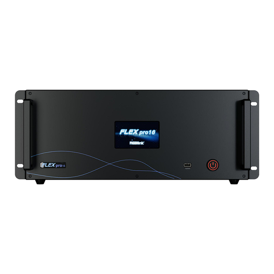
1.2 Product Overview FLEXpro16 is a high-performance video image processing system with pure hardware FPGA processing architecture. The whole machine adopts modular configuration, plug-in card structure, can be flexibly configured according to user needs, input and output cards to meet the needs of a variety of video applications on site. -
Page 10: Key Features
● Static and Dynamic OSD titles ● Seamless switch between inputs and outputs ● Dual HD multi-view output ports. Simultaneous monitoring up to 16 input/output sources ● Support monitoring of up to 16 Dante audio input channels ● Dual power module backup FLEXpro16 User Manual... -
Page 11: Front Panel
Menu includes: Device, Settings,Load, Upgrade, Language and Version. The user can check temperature in the lower right corner. If temperature of the rear panel or output module exceeds 70°C, the LCD screen will pop up a high-temperature warning, displaying FLEXpro16 User Manual... - Page 12 100°C. 1.4.1.1 Device Click [Device], the LCD screen will show the rear panel of FLEXpro16. Green indicates successful connection with valid signal or output, red indicates connection but no input, and white represents unconnected status.
- Page 13 Click [Communication Settings] to do settings of IP and Serial Communication. Click [IP Settings] to enter the following interface to check IP address of FLEXpro16. The user can turn off DHCP to manually set the IP address, subnet mask and gateway. Then click [Save] to confirm.
- Page 14 Default to Auto-Adjustment Mode. If the users need to manually control the fan speed, turn off Auto-Adjustment Mode to adjust fan speed. If temperature of the device exceeds 70℃, a prompt will pop up as shown above. Factory Reset FLEXpro16 User Manual...
- Page 15 After reset is completed, the screen will display "Reset completed, please restart device", as shown below: 1.4.1.3 Load Click [Load] to enter the interface of loading bank. Page: 16 pages in total Bank:16 banks in each page. Yellow background: current bank; Green background: bank saved; FLEXpro16 User Manual...
- Page 16 If no USB disk is inserted, the interface will prompt the user to insert the USB disk for upgrading. Insert a USB disk, click “Upgrade”and then "Confirm" to start upgrading. After upgrade is completed, click [Confirm] to restart FLEXpro16. FLEXpro16...
- Page 17 1.4.1.5 Chinese/English Click [Chinese/English] to set system language as English or Chinese. 1.4.1.6 Version Click [Version] for an overview of communication module, input module and output module information. FLEXpro16 User Manual...
-
Page 18: Rear Panel
● Support dual power module backup Interface Protector Used to pull out device, fix cables and protect interfaces from collision Increase the safety and reliability, and avoid accidents such as fire and Ground Screw explosion caused by static electricity. FLEXpro16 User Manual... -
Page 19: Dimension
1.6 Dimension Dimension of FLEXpro16 : 483.4mm x 376mm x 178mm. FLEXpro16 User Manual... -
Page 20: Chapter 2 Install Your Product
Chapter 2 Install Your Product 2.1 Plug in Power Connect power and FLEXpro16 with standard power cord. 2.2 Turn on Your Product Connect input and output signal sources, then slightly press the power button on the front panel to turn on FLEXpro16. -
Page 21: Chapter 3 Use Your Product
Chapter 3 Use Your Product 3.1 CPX Controls FLEXpro16 3.1.1 CPX Front Panel Users can refer to the following table for more details of button operation. Description LCD panel for menu operation 1.Light ON indicates other buttons are available; Light OFF indicates other buttons are locked. - Page 22 2.Initial state: All input and output button lights are OFF. Users need to choose one input button first and then the corresponding output button light will be ON. Users can press other output buttons for matrix switch. FLEXpro16 User Manual...
-
Page 23: Cpx Rear Panel
4. Used as Numeric Keys under menu control; 1-9 indicate number 1-9, 10 indicates number 0. 3.1.2 CPX Rear Panel Description DV 12V power socket. RS 232 port. Connect two FLEXpro16 devices to the same switch, and CPX can control FLEXpro16 User Manual... -
Page 24: Connect Cpx And Flexpro16
Please connect the input signals, such as camera, computer or other device, to the input port of the FLEXpro16 via correct cable; Please connect the output port to monitor via correct cable. After successful connection, power on FLEXpro16 and CPX. (Use the standard 12V power adapter to connect CPX and power socket in order to boot up CPX.) -
Page 25: Use Function Keys
The default IP Address of CPX is 192.168.0.200 and FLEXpro16 is 192.168.0.100. 1. If IP address of FLEXpro16 and CPX have not been modified before, that is, the IP of CPX and FLEXpro16 are in the same LAN, you can directly connect CPX and FLEXpro16 via a network cable. - Page 26 Step 2: Select [OUT 5], [OUT 5] light will be ON and the output port 5 will display input signal 1. The input and output relationship will change accordingly on LCD screen. Example 2: Switch input 1 to output 7 and output 8 (Input signal 1 been used in output port 5 already.) FLEXpro16 User Manual...
- Page 27 Press [ OSD ] key on the panel to enter OSD Mode and the light of [ OSD ] is ON. In OSD Mode, users can use numeric key [IN 1-16] to load OSD 1 to output ports 1-16; and [OUT 1-16]to load OSD 2 to output ports 1-16. FLEXpro16 User Manual...
- Page 28 Step 1: Press [IN 10] and the light will be on to indicate OSD 1 has been loaded on output port 10. Step 2: Press [OUT 12] and the light will be on to indicate OSD 2 has been loaded on output port FLEXpro16 User Manual...
- Page 29 Step 2: Press [OUT 1] to remove output signal 1 from the group. Light of [OUT 1] will turn OFF. (Notice: Suppose that [OUT 1], [OUT 3] and [OUT 5] displayed the signal 8 at first, and [OUT 1] continues to display the signal 8 after been removed from the output group. ) FLEXpro16 User Manual...
- Page 30 Example 1:The initial status is that no scene has been used before . If you want to enter to scene 1, refer to the following steps. Step 1: Press [LOAD] to enter non-saved scene mode, and the light will be on. Step 2: Press [OUT 1] to load Scene 1. FLEXpro16 User Manual...
-
Page 31: Use Main Menu
[ Admin ]. Under menu operation, [ SAVE ], [ OSD], [ LOAD] and [ MATRIX ] are used as Direction Keys, which indicate Up, Down, Left and Right respectively; and [ GROUP OUT] is used as Confirm Key. FLEXpro16 User Manual... - Page 32 IP address is editable. You can key in numbers in [OUT 1~16] area for IP Modification. Device 1/2 IP: User can perform operations like IP check or IP modification of FLEXpro16 in this interface. If IP modification is needed, please press the [GROUP OUT] key firstly. * mark indicates IP address is currently editable.
- Page 33 Page 1 by default.For example, If you need to switch Scene 1 on Page 2, please do as follows: [LOAD]-[IN 2]-[OUT 1]. 3.1.5.3 OSD Press MENU to enter main menu interface, choose [ OSD ] to enter the sub-menu. FLEXpro16 User Manual...
- Page 34 English and Chinese are available. If you choose English, just select English and then press [GROUP OUT] key to confirm, the user interface will automatically switch from Chinese to English. 3.1.5.5 Reset Press MENU to enter main menu interface, choose [ Reset ] to restore the device configuration to the default parameters. FLEXpro16 User Manual...
- Page 35 Reset Local Machine and Target Machine: Reset information of CPX and controlled device (such as FLEXpro16) Reset Local Machine:Reset information of CPX only. Notice: All parameters will be restored to default parameters, which include but not limited to device IP, EDID, preset scenes, etc.
- Page 36 1680 × 1050@60, 1920 × 1080@60, 1920 × 1080@30, 1920 × 1080@50, 1920 × 1080@50i, 1920 × 1080@60i Communication Preview Mode: ONLY Preview Input Mode is supported. 4x4, 3x3, 2x2, 2+8, 2+4 layouts for you to choose from. FLEXpro16 User Manual...
-
Page 37: Xpose 2.0 Installation
Monitor: Resolution must be 1680×1050 pixel or above(it can not display normally if the resolution is lower than 1680×1050) CPU: i5 and above 1. Double click , it will pop-up the installer language box, select the language, for example, select “English”, and click “OK” to confirm. FLEXpro16 User Manual... - Page 38 3. Click “Browse...” to select the XPOSE software install location. Click “Install”. 4. During installation, it will pop up the window of Install Shield Wizard for Virtual Com port. 5. Click “Next”. 6. Then click “Install", as shown in the figure. FLEXpro16 User Manual...
-
Page 39: Xpose 2.0 Operation
8. Click “Finish” and is ready to run the XPOSE software. 3.3 XPOSE 2.0 Operation 3.3.1 Login in XPOSE Double click icon to enter the log on interface shown in the right: FLEXpro16 User Manual... -
Page 40: System Setting
Click Find Device: New version of XPOSE 2.0 is blank default in Find Device. Users are supposed to choose the device needed in Find Device. System Info: Check current software version and choose system language you need. FLEXpro16 User Manual... - Page 41 Users can also Save The Keyboard Setting As Script. Scrip Set File Path: Save the current Keyboard Settings in the script to the local path. File Name: script file name Load Script: Load/Delete Click Return to back to <System Setting> FLEXpro16 User Manual...
- Page 42 On Status for operation. For operating device for the first time, or device upgrade, or factory reset, XPOSE defaults to log in as Administrator with name defaults to Admin, and PWD defaults to admin. is displayed in Chosen Devices. FLEXpro16 User Manual...
- Page 43 Edit: Edit user name and password built. Delete: Delete user name and password built. Authorization Set: Functions on XPOSE 2.0 on this computer that the users are allowed to operate. Click the green block to remove the function not to be permitted. FLEXpro16 User Manual...
-
Page 44: Output|Input|Overview
2. Interface Color Description: 1) Green: normal signal; 2) Yellow: abnormal signal; White: no signal. (Due to hardware limitation, SDI output interface always displays white where there is or isn’t a signal.) FLEXpro16 User Manual... - Page 45 Module Format Range: is to set the resolution of all output ports of the selected module to be the same. The resolution of other modules can be set to different resolutions. Resolutions can be chosen as shown in the right figure. FLEXpro16 User Manual...
- Page 46 Input Text: The exact content of the text. The user can customize OSD content or choose Clear OSD (If the setting is not desired) or Close All OSD. After all settings done, click <Set> and the OSD will be displayed on the screen. FLEXpro16 User Manual...
- Page 47 <Property> and <EDID>. User can set Property Setting Input Port:chosen port Scale: X/Y:the starting horizontal and vertical position. Width/Height : the horizontal and vertical size of scale. Crop: Support cropping for position, height and width. FLEXpro16 User Manual...
- Page 48 Width/Height/Frequency: type in custom parameters to meet your needs. Communication Board with PVW When there is communication Board with PVW input module installed on FLEXpro16, you can click HDMI port for following operations. Frame Status: Turn on status to set frame color.
- Page 49 Output Module Info: Users can check current output module information. Support auto/manual setting. Show IP Address, Netmask, Gateway. Fan Control Support auto/manual setting. Fan Speed: 0-100. Notice: To avoid insufficient heat dissipation, the recommended manual fan speed is not less than FLEXpro16 User Manual...
-
Page 50: Display Management
Display System is for users to set layout of outputs. Click first and then to enter the interface. Container Container here means the Display Area, for example it could be a formed LED screen or an array of LCDs. FLEXpro16 User Manual... - Page 51 Each mode is marked in different color and provided with fitted templates. Users can do operations like splice under different modes. FLEXpro16:Split Mode and Matric Mode (by default) optional. Matrix Mode: No need of recreating a container after changing resolution.
-
Page 52: Layer Management
The output being replaced will turn from gray to white in the list. Display System FLEXpro16 allows users to edit the name of the Display Area that has been created just click 3.3.5 Layer Management Layer Management is designed to manage the layer of each monitor. - Page 53 Choose one layer needed to be adjusted, and type in its position and size. this icon means data related, when width is changed, height will be changed as same proportion. this icon means data not related, width and height need to be filled respectively. FLEXpro16 User Manual...
- Page 54 2. Turn on H.265 and users can preview the image. As shown in the right figure, the interface shows that Layer Preview, Input Preview, Scene Preview are enabled. Note: H.265 is the master switch. If the user turns on H.264 first, it cannot be set successfully. FLEXpro16 User Manual...
- Page 55 Layer Backward Layer to Top Paste Selected Layer Forward Select All Cancel Selected Layer to Bottom Copy Selected Delete Selected Note: One signal occupies one layer (4K signal occupies four layers), signal can be dragged into container repeatedly. FLEXpro16 User Manual...
-
Page 56: Preset Management
Select a bank and click Preset Name, fill in the blank after New Preset Name to rename a Preset (Bank) Click the color block after Color Selection and choose a new color for the boarder of chosen bank. FLEXpro16 User Manual... - Page 57 Steps are as follows: 1、Turn on “Schedule Mode”; 2、Choose “Times Loop” in Loop Mode; 3、Choose the BANK ; 4、Fill in the “Duration” ; 5、Click “OK”. Users can click to edit and to delete. After settings done, turn on “Loop Switch”. FLEXpro16 User Manual...
-
Page 58: Chapter 4 Order Code
Chapter 4 Order Code 4.1 Product Code 710-1016-01-0 FLEXpro16 4.2 Module Code 4.2.1 Input Modules 790-1016-01-0 Quad HDMI 1.3 Input Module 790-1016-02-0 Dual DP 1.2 & Dual HDMI 2.0 Input Module 790-1016-03-0 Quad 3G-SDI Input Module 790-1016-04-0 Single IP Input Module 4.2.2 Output Modules... -
Page 59: Chapter 5 Appendix
Chapter 5 Appendix 5.1 Contact Us FLEXpro16 User Manual... -
Page 60: Terms & Definitions
●HDMI: High Definition Multimedia Interface: An interface used for the transmission of uncompressed high definition video, up to 8 channels of audio, and control signals, over a single cable. ● HDMI 1.3: Released on June 22 2006, and increased the maximum TMDS clock to 340 MHz (10.2 Gbit/s). FLEXpro16 User Manual... - Page 61 ●Single-mode Fiber: Fiber that support a single mode are called single-mode fibers. Single-mode fibers are used for most communication links longer than 1,000 meters (3,300 ft). FLEXpro16 User Manual...
- Page 62 ● USB 3.2: Super Speed USB with 3 varieties of 3.2 Gen 1(original name USB 3.0), 3.2Gen 2(original name USB 3.1), 3.2 Gen 2x2 (original name USB 3.2) with speed up to 5Gbps,10Gbps,20Gbps respectively. USB version and connectors figure: Type A Type B Mini A Mini B Micro-A Micro-B Type C USB 2.0 USB 3.0 FLEXpro16 User Manual...
- Page 63 NDI is commonly found in broadcast applications. ●RTMP: Real-Time Messaging Protocol (RTMP) was initially a proprietary protocol developed by Macromedia (now Adobe) for streaming audio, video and data over the Internet, between a Flash player and a server. FLEXpro16 User Manual...
- Page 64 ●Brightness: Usually refers to the amount or intensity of video light produced on a screen without regard to colour. Sometimes called black level. ●Contrast Ratio: The ratio of the high light output level divided by the low light output level. In theory, the FLEXpro16 User Manual...
- Page 65 ●PIP: Picture-In-Picture. A small image within a larger image created by scaling down one of image to make it smaller. Other forms of PIP displays include Picture-By-Picture (PBP) and Picture- With-Picture (PWP), which are commonly used with 16:9 aspect display devices. PBP and PWP image formats require a separate scaler for each FLEXpro16 User Manual...
-
Page 66: Revision History
First release Aster All information herein is Xiamen RGBlink Science & Technology Co Ltd. excepting noted. is a registered trademark of Xiamen RGBlink Science & Technology Co Ltd.While all efforts are made for accuracy at time of printing, we reserve the right to alter otherwise make change without notice.
Need help?
Do you have a question about the FLEXpro16 and is the answer not in the manual?
Questions and answers