EMS FIRE SYSTEM 5000 User Manual
Hide thumbs
Also See for FIRE SYSTEM 5000:
- Operating manual (40 pages) ,
- Step-by-step manual (34 pages) ,
- User manual (28 pages)

Subscribe to Our Youtube Channel
Related Manuals for EMS FIRE SYSTEM 5000


Summary of Contents for EMS FIRE SYSTEM 5000
- Page 1 E.M.S. 5000 YSTEM ONTROL ANEL ANUAL MODEL SHOWN. 5096 Issue. 5 June 2002...
-
Page 2: Table Of Contents
E.M.S Group System 5000 Contents 1.0 Introduction..................................... 2 2.0 System Design..................................2 3.0 Equipment Required................................2 4.0 Fire Alarm Procedures................................2 5.0 Controls and Indications ................................3 STATUS LAMPS..................................4 KEYSWITCH.................................... 4 CONTROL BUTTONS................................4 6.0 Panel Conditions.................................. -
Page 3: Introduction
1.0 Introduction. This manual contains all the information needed to operate the EMS System 5000. The instructions given in this manual must be followed when using the system. Should you have any questions regarding the operation of this system, refer these to your installer. -
Page 4: Controls And Indications
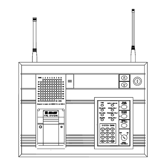
Zone Lamps, The Display itself and the UP / DOWN Scroll Buttons. Zone Lamps UP / DOWN Buttons Front Panel Lock ZONE EMS FIRE SYSTEMS LTD System Clear Thu Dec28 13 : 22 20 Character 4 Line Display ZONE... -
Page 5: Status Lamps
E.M.S Group System 5000 STATUS LAMPS. There follows a description of the function of each Status Lamp. FIRE:-This lamp illuminates when a Fire Alarm occurs. PRE -ALARM:- System 5000 Smoke and Heat Detectors have “built in” intelligence and will, for example, register a sharp rise in temperature. -
Page 6: Panel Conditions
E.M.S Group System 5000 Panel Conditions Under “Non Alarm” conditions the panel will indicate that the system is clear. The display will show the date and time, as well as how to gain access to the system. At this time the display will alternate between the two following displays. Status Normal 0 for Access Time... - Page 7 E.M.S Group System 5000 After a short while, or after a key has been pressed, the display will change Panel In Access to show, figure 8. Date Time Figure 8 This indicates that the “Panel Controls” keyswitch is still in the Status Normal ON position.
-
Page 8: Isolating A Device After An Alarm Event
E.M.S Group System 5000 8.0 Isolating A Device After An Alarm Event If a device develops a fault, and engineering support is not immediately available, it is possible to isolate a device by carrying out the following sequence of operations. If the device is still in alarm, pressing Device NOT CLEAR : the RESET / LED TEST button will... -
Page 9: Isolating A Device Prior To An Alarm Event
E.M.S Group System 5000 Scroll down until “Status is”, is Number is : 005 between the > and < characters, as > Status is : ACTIVE < shown in figure 18. Zone is : 01 YES = Select Time Figure 18 Press the YES key. - Page 10 E.M.S Group System 5000 Press YES. The display will change to ** Fire System ** show, figure 23. > Dev.Isolate/Test < Net. Isolate/Test YES = Select Time Figure 23 Press YES. The display will change to **Device Status ** show, figure 24. >...
-
Page 11: Re-Instating An Isolated Device
E.M.S Group System 5000 10.0 Re-instating An Isolated Device Turn the Panel Controls keyswitch to the ON position, this will result in the Panel In Access display changing to show, figure 29. Date Time Figure 29 Press the 0 key. The display will Options change to show, figure 30. -
Page 12: Isolating A Network Device
E.M.S Group System 5000 Enter the device number to be re- **Device Status ** instated (in the example it is device > Number is : 005 < number 005). Press the YES key. The Status is : ISOLATE display will change to show, figure 35. YES = Select Time Figure 35... - Page 13 E.M.S Group System 5000 01 FIRE ALARM TOT 01 After a short time period, the display will change. RADIO CALLPOINT This shows the device concerned is number 28, a call point, allocated to ZONE 23 P :04DEV :028 zone 23 on Network Panel number 04. Figure 40 Fire System Press the 0 key.
-
Page 14: Re-Instating An Isolated Network Device
E.M.S Group System 5000 Panel Type : PAN Enter the device number to be > Panel < isolated (in the example it is device Device number 028). Press the YES key. The display will change to show, figure 47. YES= Select Time Figure 47 Device... - Page 15 E.M.S Group System 5000 Logging Scroll down until “ Fire System > Fire System Opts < Opts’’ is shown between the > and < Remote Access characters. The display will show, figure 53. YES= Select Time Figure 53 Fire System Press YES.
- Page 16 E.M.S Group System 5000 Panel Type : PAN Enter the device number to be > Panel < re- instated (in the example it is device Device number 028). Press the YES key. The display will change to show, figure 60. YES = Select Time Figure 60...
-
Page 17: Viewing The Systems Event Log
E.M.S Group System 5000 13.0 Viewing The Systems Event Log It is possible to view events after they have been reset by interrogating the systems log. If for any reason the events can not be reset the device concerned must be isolated before the log can be viewed, (see section 8 for details). The log holds 1000 events and can be viewed in varying degrees of detail ranging from, showing the last incident, viewing a particular dates logged events, to actually viewing the complete systems log. -
Page 18: Routine Testing
E.M.S Group System 5000 Enter the date required to be viewed in dd / mm / yy format ( in this example ------------------------------------------ On 01/01/97 At 00:00 01 / 01 / 97 has been selected ) . Press New Day of 01/01/97 YES. -
Page 19: Panel Alarm & Fault Displays
E.M.S Group System 5000 16.0 Panel Alarm & Fault Displays The following section contains useful information regarding screen shots and descriptions of alarm and fault conditions and possible causes. If there is more than one alarm shown the " and ! buttons on the control panel can be used to display each event. - Page 20 E.M.S Group System 5000 TAMPER This display shows a tamper alarm has been activated from the device shown on the controllers display. The following alarm screen will be shown; Indicates the total Indicates the alarm number of system → ← alarms. 01 TAMPER TOT 01 type and number.
- Page 21 E.M.S Group System 5000 FAULT: BT This fault can be displayed for a number of reasons. Firstly there are no batteries present in the unit, secondly the batteries are not charging and lastly the battery voltage is low. The battery charging and low voltage readings are checked once a day at midnight, whilst if batteries are not present in the unit the fault will be displayed immediately.
-
Page 22: Menu Structure & Glossary
E.M.S Group System 5000 FAULT: OL This fault shows the controller is currently Off Line on either a hardwired or radio networked system. This indicates the control panel is no longer communicating with the network system. If this has taken place the following fault screen will be shown; Indicates the faults number. - Page 23 E.M.S Group System 5000 Passwords To enter the Passwords Menu use the " and ! keys to position “Passwords” between the > and < characters on the display and then press the YES key. The following options will now be available. User Log On: This option invites a PIN (Personal Identification Number) to be entered.
- Page 24 E.M.S Group System 5000 View The Date: This allows the date programmed into the system to be viewed from the display. The date is used for the recall of the log and the BST/GMT change over. Set The Date: This allows the date programmed into the system to be changed on the display. View BST/GMT: This allows the dates programmed in for the time change to be viewed.
- Page 25 E.M.S Group System 5000 ask for a zone number to be entered, when this has been done the system will automatically show the settings for that particular zone. Valid zone numbers range from 1 -96. A full explanation of the zone variations is detailed below. All:- With the zone status set to ALL, any device allocated to that zone will activate all of the sounders in the system when a fire signal is sent.
- Page 26 E.M.S Group System 5000 Notes: EMS FIRE SYSTEMS LIMITED UNIT 11, WEST TRADING ESTATE,HERNE BAY, KENT CT6 8JZ. TEL: (01227 369570) FAX: (01227 369679)
Need help?
Do you have a question about the FIRE SYSTEM 5000 and is the answer not in the manual?
Questions and answers