EMS FirePoint 5000 Communications Manual
Radio lan
Hide thumbs
Also See for FirePoint 5000:
- Operating manual (40 pages) ,
- Step-by-step manual (34 pages) ,
- User manual (28 pages)
Table of Contents
Advertisement
Quick Links
Advertisement
Table of Contents

Related Manuals for EMS FirePoint 5000


Summary of Contents for EMS FirePoint 5000
- Page 1 5000 RADIO LAN COMMUNICATION GUIDE...
-
Page 2: Table Of Contents
9. DIAGNOSTICS/MONITORING NODES ................10 10. TO SET UP MIMICS/REPEATERS ON THE SYSTEM: ............11 11. STEP BY STEP SOFTWARE CONFIGURATION:..............12 12. CONTROLLER INFORMATION: ..................20 ©2015 EMS Security Group Ltd. All rights reserved. TSD234 Iss 3 25/06/15 AJM... -
Page 3: Introduction
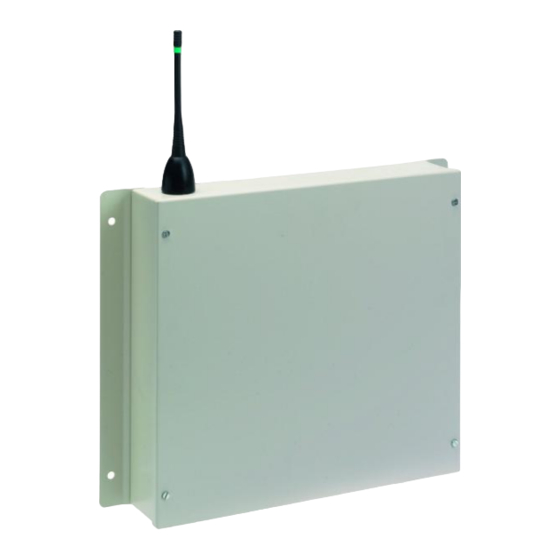
5000 FirePoint control panel manuals. Radio LAN Modules are used for radio networking EMS system control panels together. The Radio LAN Module is hardwired to it’s allocated control panel via a 2 core screened fireproof cable. -
Page 4: Tools & Equipment
3. Electrical Installation The Radio LAN unit should be hardwired to the EMS 5000 FirePoint Control Panel, as shown in the supplied drawing PO3265. The following paragraphs outline the installation in a step-by-step format. - Page 5 EMS 5000 FIREPOINT ©2015 EMS Security Group Ltd. All rights reserved. TSD234 Iss 3 25/06/15 AJM...
- Page 6 Please Monitor Node Monitor Node refer to the table (Numbers 2-30) ^^^^^^^^^^^^^^^^^^ on page 13 for Number > _ Yes = Finish TIME the applicable value ©2015 EMS Security Group Ltd. All rights reserved. TSD234 Iss 3 25/06/15 AJM...
-
Page 7: Factory Supplied Pre-Programmed Systems
Scroll down to ”Reset System” and press the “YES” key followed by the “0” key. Scroll down to “Serial Comms” and press the “YES” key. Scroll down to “Re-start bus and press the “YES” key. ©2015 EMS Security Group Ltd. All rights reserved. TSD234 Iss 3 25/06/15 AJM... -
Page 8: Should The Radio Lan Go Offline
Press the “YES” key, enter 221100 then press the “YES” key. Scroll down to “Reset System” and press the “YES” key followed by the “0” key. Scroll down to “RADIO LAN” and press the “YES” key. ©2015 EMS Security Group Ltd. All rights reserved. TSD234 Iss 3 25/06/15 AJM... -
Page 9: Monitoring Nodes (Panels)
“Advanced” menu, listed above the “Clear Missed Polls” option. By entering the “Node table”, each node can be viewed for their ONLINE/OFFLINE status and their number of missed polls. ©2015 EMS Security Group Ltd. All rights reserved. TSD234 Iss 3 25/06/15 AJM... -
Page 10: Diagnostics/Monitoring Nodes
PPT being the “Poll Interval” value i.e. time between polls, and the PTT being the “Poll Timeout” value which considers the panel offline when 0 is reached. ©2015 EMS Security Group Ltd. All rights reserved. TSD234 Iss 3 25/06/15 AJM... -
Page 11: To Set Up Mimics/Repeaters On The System
This process can be followed for up to three nodes. The selected nodes will now be set as mimics. You can now exit the menu and return to the main screen. ©2015 EMS Security Group Ltd. All rights reserved. TSD234 Iss 3 25/06/15 AJM... -
Page 12: Step By Step Software Configuration
| Pager Setup Yes= Select Time |* Serial Comms > Device Table < Press the “YES” key. The screen will now display: | Re-start bus Yes= Select Time ©2015 EMS Security Group Ltd. All rights reserved. TSD234 Iss 3 25/06/15 AJM... - Page 13 Time | * Remote Setup * | Press the “YES” key. The screen will now display: > Reply Baudrate < | Port to use Yes= Select Time ©2015 EMS Security Group Ltd. All rights reserved. TSD234 Iss 3 25/06/15 AJM...
- Page 14 > Enable Receiver < The screen will display: | Enable Collector | Yes= Select Time | Enable Receiver | > Enable Collector < Monitor Traffic | ©2015 EMS Security Group Ltd. All rights reserved. TSD234 Iss 3 25/06/15 AJM Yes= Select Time...
- Page 15 “YES” Key followed by the “NO” key. The screen | Send Test Yes= Select Time should now display: | Network Router > Radio LAN < ©2015 EMS Security Group Ltd. All rights reserved. TSD234 Iss 3 25/06/15 AJM | Fire DB Yes= Select Time...
- Page 16 |LAN Module Nua:00| Yes= Select Time Note: The Site ID is factory set, and can only be altered by entering an EMS engineering password. Note: This must match on all control panels on the radio board network for communication to take place.
- Page 17 Note: time to be input to the poll interval timer value varies depending number slave panels within system. The time can be calculated using table below: - ©2015 EMS Security Group Ltd. All rights reserved. TSD234 Iss 3 25/06/15 AJM...
- Page 18 EMS 5000 FIREPOINT ©2015 EMS Security Group Ltd. All rights reserved. TSD234 Iss 3 25/06/15 AJM...
- Page 19 Turn the control keyswitch to the off Status Normal position and the screen will display: Date Time Installation and programming of the Radio LAN setup should now be complete. ©2015 EMS Security Group Ltd. All rights reserved. TSD234 Iss 3 25/06/15 AJM...
-
Page 20: Controller Information
151.33mA in standby Battery space: 1 x 12volt 7Ah batteries (supplied) EMS only recommend: Yucel Model No: NP7-12 battery equivalent specification Recommended battery 5 years replacement intervals: ©2015 EMS Security Group Ltd. All rights reserved. TSD234 Iss 3 25/06/15 AJM... - Page 21 EMS 5000 FIREPOINT ©2015 EMS Security Group Ltd. All rights reserved. TSD234 Iss 3 25/06/15 AJM...
- Page 22 EMS 5000 FIREPOINT ©2015 EMS Security Group Ltd. All rights reserved. TSD234 Iss 3 25/06/15 AJM...
Need help?
Do you have a question about the FirePoint 5000 and is the answer not in the manual?
Questions and answers