
Related Manuals for PLANEPRINT Falcon Realistic Bird motor


Summary of Contents for PLANEPRINT Falcon Realistic Bird motor
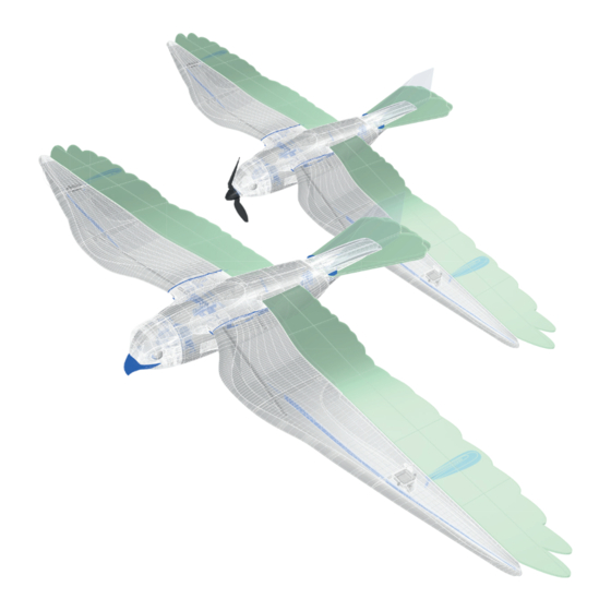
- Page 1 Realistic Bird model – motor and glider version www.planeprint.com the ONLY place where you can get original Planeprint STL fi les legally!
- Page 2 LWPLA Carbon Foam board FALCON PRINTING & ASSEMBLING MANUAL © PLANEPRINT...
- Page 3 Rod connection hole 1 mm • Fabric tape or fabric • Adhesive tape • Self adhesive velcro tape * These Foam parts cannot be printed for weight reasons, LW PLA is much heavier than foam. FALCON PRINTING & ASSEMBLING MANUAL © PLANEPRINT...
- Page 4 Cutting template for the Foam parts Print out these pages on A4 paper and cut out the templates. For the Aileron, cut them out along the red dotted line and glue the parts together exactly. Attach them to the foam board and cut the foam parts with a sharp knife.
- Page 5 Aileron/Wing (two pieces mirror-inverted)
- Page 6 Aileron/Wing (two pieces mirror-inverted)
- Page 7 There are different versions here! You can decide which one you want to build in the manual further down.
- Page 8 Elevator Foam rigid version This opening is ONLY required if the rudder is built in the foam version.
- Page 9 Elevator spread version (two pieces mirror-inverted) Elevator spread version This opening is ONLY required if the There must be rudder is built in the an opening here foam version.
- Page 10 Fold here Rudder Overhead transparency version...
- Page 11 This manual is constantly being improved and supplemented, we recommend downloading the latest version from our website before building. To print all PLANEPRINT models you need to set some basic profiles in Cura (If you use another slicer, please set the same parameters).
- Page 12 Please note the additional settings for the individual parts! P1_Setting gauges-fn.stl MATERIAL PLA, Weight: ~ 7 g ADDITIONAL SETTINGS Wall Line Count/Perimeters: 20 P1_AIL horns-fn.stl MATERIAL PLA, Weight: ~ 3 g ADDITIONAL SETTINGS None required FALCON PRINTING & ASSEMBLING MANUAL © PLANEPRINT...
- Page 13 ADDITIONAL SETTINGS None required P1_Center parts-fn.stl MATERIAL PLA, Weight: ~ 17 g ADDITIONAL SETTINGS Wall Line Count/Perimeters: 3 Remove support. Remove support. Please be careful with the knife! Please be careful with the knife! FALCON PRINTING & ASSEMBLING MANUAL © PLANEPRINT...
- Page 14 The information about the basic settings you can fi nd on our website at PRINT. Please note the additional settings for the individual parts! P1_Clips-fn.stl MATERIAL PLA, Weight: ~ 1 g ADDITIONAL SETTINGS None required P1_Head mount-fn.stl MATERIAL PLA, Weight: ~ 2 g ADDITIONAL SETTINGS None required FALCON PRINTING & ASSEMBLING MANUAL © PLANEPRINT...
- Page 15 Please note the additional settings for the individual parts! P1_Motor mount 16-19-fn.stl MATERIAL PLA, Weight: ~ 1 g ADDITIONAL SETTINGS None required P1_Parts-fn.stl MATERIAL PLA, Weight: ~ 6 g ADDITIONAL SETTINGS None required FALCON PRINTING & ASSEMBLING MANUAL © PLANEPRINT...
- Page 16 The information about the basic settings you can fi nd on our website at PRINT. Please note the additional settings for the individual parts! P1_Protectors-fn.stl MATERIAL PLA, Weight: ~ 2 g ADDITIONAL SETTINGS None required P1_T-connects-fn.stl MATERIAL PLA, Weight: ~ 1 g ADDITIONAL SETTINGS None required FALCON PRINTING & ASSEMBLING MANUAL © PLANEPRINT...
- Page 17 Please note the additional settings for the individual parts! P1_Tail joint 1-fn.stl MATERIAL PLA, Weight: ~ 2 g ADDITIONAL SETTINGS None required P1_Tail joint 2-fn.stl MATERIAL PLA, Weight: ~ 3 g ADDITIONAL SETTINGS None required FALCON PRINTING & ASSEMBLING MANUAL © PLANEPRINT...
- Page 18 Please note the additional settings for the individual parts! P1_Tail joint 3-fn.stl MATERIAL PLA, Weight: ~ 2 g ADDITIONAL SETTINGS None required P1_Wing Spar-fn.stl MATERIAL PLA, Weight: ~ 10 g ADDITIONAL SETTINGS None required FALCON PRINTING & ASSEMBLING MANUAL © PLANEPRINT...
- Page 19 TPU, Weight: ~ 14 g ADDITIONAL SETTINGS • Infi ll Density: 100 % You can also print this part with PLA. TPU has the advantage that it is softer and the tip cannot break off. FALCON PRINTING & ASSEMBLING MANUAL © PLANEPRINT...
- Page 20 Please be careful with the knife! P5_Body 2-fn.stl MATERIAL LW PLA, Weight: ~ 17 g TIME ~ 2 hours 40 minutes ADDITIONAL SETTINGS • Infi ll Density/Fill Density: 3 % Remove the stringing threads FALCON PRINTING & ASSEMBLING MANUAL © PLANEPRINT...
- Page 21 Please be careful with the knife! P5_Head glider-fn.stl MATERIAL LW PLA, Weight: ~ 13 g TIME ~ 2 hours 30 minutes ADDITIONAL SETTINGS • Infi ll Density/Fill Density: 8 % Remove the stringing threads FALCON PRINTING & ASSEMBLING MANUAL © PLANEPRINT...
- Page 22 LW PLA, Weight: ~ 9 g TIME ~ 1 hour 30 minutes ADDITIONAL SETTINGS • Infi ll Density/Fill Density: 3 % Remove support. Remove support. Please be careful with the knife! Please be careful with the knife! FALCON PRINTING & ASSEMBLING MANUAL © PLANEPRINT...
- Page 23 LW PLA, Weight: ~ 59 g TIME ~ 10 hours ADDITIONAL SETTINGS • Infi ll Density/Fill Density: 3 % Remove support and round the edge of the nose nicely! Please be careful with the knife! FALCON PRINTING & ASSEMBLING MANUAL © PLANEPRINT...
- Page 24 ~ 3 hours 40 minutes ADDITIONAL SETTINGS None required Remove support Remove support and round the edge and round the edge of the nose nicely! of the nose nicely! Please be careful with the knife! FALCON PRINTING & ASSEMBLING MANUAL © PLANEPRINT...
-
Page 25: Body Assembly
They must not be glued! P1_Center partsfn.stl P5_Body 1fn.stl Carbon tube Ø6*310mm P1_Center partsfn.stl P1_Partsfn.stl medium liquid P5_Body 2fn.stl New improved Tshaped interconnects P1_Tail joint 1fn.stl P1_Tconnectsgi.stl FALCON PRINTING & ASSEMBLING MANUAL PRINTING & ASSEMBLING MANUAL © PLANEPRINT © PLANEPRINT... -
Page 26: Head Assembly
Here is an example of the glider head: Space for lead P1_Head mountfn.stl Fasten the head to the body with three short P5_Head gliderfn.stl tapping screws. So you can switch between glider and motor version at any time. P4_Beakfn.stl FALCON PRINTING & ASSEMBLING MANUAL © PLANEPRINT... -
Page 27: Tail Assembly
First screw the two screws all the way in and then slightly back so that the joint (elevator) is precise but smoothrunning. P5_Tail rigid foamfn.stl P5_Tail rigid glassfn.stl P5_Tail spread foamfn.stl P5_Tail spread glassfn.stl P1_Partsfn.stl FALCON PRINTING & ASSEMBLING MANUAL © PLANEPRINT... - Page 28 Fold the rudder at the top and insert it into the slots of the tail part. Allow thin CA glue to run into the slots and do not use activator spray to prevent clouds from forming. FALCON PRINTING & ASSEMBLING MANUAL © PLANEPRINT...
- Page 29 Elevator spread version Elevator spread version For the movement of the feathers to work, the foam must have a smooth surface! Bevel the edge slightly at these points so that the foam parts cannot tilt. FALCON PRINTING & ASSEMBLING MANUAL © PLANEPRINT...
- Page 30 (they must cross) the body (they must cross) Attach the tail to the joint in the body using two tapping screws. FALCON PRINTING & ASSEMBLING MANUAL © PLANEPRINT...
-
Page 31: Wing Assembly
P5_Wings 3fn.stl thin liquid Screw the tension belt into the P1_Wing Sparfn.stl wing and insert the carbon tubes. They do not need to be glued. Carbon tube Ø6*70mm P4_Tension beltfn.stl Carbon tube Ø6*310mm FALCON PRINTING & ASSEMBLING MANUAL © PLANEPRINT... - Page 32 POR, let it dry and then glue the strip to the wing and aileron. Fabric strip The gap allows the outer part to move without a visible aileron. The gap allows the outer part to move without a visible aileron. FALCON PRINTING & ASSEMBLING MANUAL © PLANEPRINT...
-
Page 33: Wing Servo
Glue the control horn onto the aileron as shown in the picture below and fi nally, if everything is set up correctly, the fabric servo cover. P1_AIL hornsfn.stl FALCON PRINTING & ASSEMBLING MANUAL © PLANEPRINT... -
Page 34: Motor Mount
P5_Head motorfn.stl P1_Motor mount 1619fn.stl Glider head There is room for lead in the beak. Position the receiver battery as far forward as possible to achieve the correct CG in combination with the lead. FALCON PRINTING & ASSEMBLING MANUAL © PLANEPRINT... - Page 35 (the PLA can become soft!). This is usually not a problem with light colors. FALCON PRINTING & ASSEMBLING MANUAL © PLANEPRINT...
- Page 36 Here you can move the battery forwards or backwards until the CG fits. The tension belts are attached here FALCON PRINTING & ASSEMBLING MANUAL © PLANEPRINT...
-
Page 37: Technical Specifications
(28 mm/1.1 inch behind the leading edge) Do not forget to check if the wings are exactly in ballance in the roll axis. If one wing is heavier, correct this with a small weight on the wingtip. FALCON PRINTING & ASSEMBLING MANUAL © PLANEPRINT... -
Page 38: Basic Setting
15 mm up 15 mm down RUDDER 60 mm left 60 mm right (for some remote EXPO ELEVATOR 30 % controls a minus has to be in front AILERON 20 % of the number) RUDDER FALCON PRINTING & ASSEMBLING MANUAL © PLANEPRINT... -
Page 39: Flying Tips
But don‘t forget to always pay atten- series of microstalls. tion to the correct CG! Please be aware of wildlife and fly the Falcon only in areas where it is allowed! FALCON PRINTING & ASSEMBLING MANUAL © PLANEPRINT... - Page 40 3D printing Always keep the transmitter switched on when the model will not be replaced by PLANEPRINT.com in any way. is switched on. When operating, always keep a safe distance from your Always remove the battery before disassembling the model.
Need help?
Do you have a question about the Falcon Realistic Bird motor and is the answer not in the manual?
Questions and answers