
Related Manuals for Mecmesin OmniTest 0.5


Summary of Contents for Mecmesin OmniTest 0.5
- Page 1 Published on Mecmesin Support (https://help.mecmesin.com) Home > OmniTest Single Column Test Systems User Manual Support Product OmniTest Revision ID 12804 Manual 431-959...
- Page 2 OmniTest Single Column Test Systems User Manual 431-959 431-959 July 2023 July 2023...
- Page 3 OmniTest™ and VectorPro™ are both registered trademarks of Mecmesin Ltd. OmniTest™ and VectorPro™ This reference manual covers the operation of Mk1 and Mk2 OmniTest 0.5, OmniTest 1.0, OmniTest 2.5, OmniTest 0.5, OmniTest 1.0, OmniTest 2.5, OmniTest 5 and OmniTest 7.5 OmniTest 5 OmniTest 7.5 force test systems, intended for use with Mecmesin enhanced load sensors,...
- Page 4 2.1.2 Caution The caution caution icon indicates a situation or condition that could cause the equipment to malfunction leading to possible damage. 2.1.3 Information The information information icon indicates additional or supplementary information about the action, activity or application.
- Page 5 Attaching Grips and Fixtures Setting the Limit Stops Enhanced Load Sensor (ELS) Setup Mounting an ELS to an OmniTest 0.5, 1.0, 2.5 and 5 (Dovetail bracket) Mounting an ELS to an OmniTest 7.5 Connecting an ELS to the OmniTest Stand...
- Page 6 Information Automatic ELS Firmware Update OmniTest Series Specification OmniTest 0.5 Dimensions OmniTest 1.0 Dimensions Omnitest 2.5 Dimensions OmniTest 5 Dimensions OmniTest 7.5 Dimensions Declaration of Conformity...
-
Page 7: System Diagrams
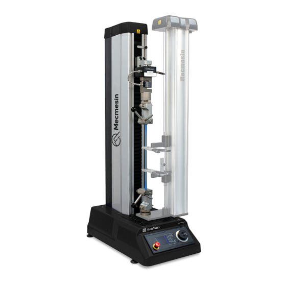
Emergency-stop switch OmniTest 0.5, 1.0, 2.5 and 5 System Details The OmniTest 0.5,1.0, 2.5 and 5 test systems use a conventional Mecmesin dovetail mount fitting on the moving crosshead. The OmniTest 0.5 has a maximum force capacity up to 500N (112.4 lbf). - Page 8 Dovetail fitting on an OmniTest 5 Dovetail fitting on an OmniTest 5 The dovetail fitting will accommodate both the ELS ELS series and ELS ‘S’ ELS ‘S’ series load cells. For more information relating to individual ELS types please see the following section 'Mounting an ELS to an OmniTest 5 Mounting an ELS to an OmniTest 5 OmniTest 7.5 System Details...
-
Page 9: Rear Connectors Panel
Guard Interlock connector and Override Key Extensometer input port Digital I/O port (not currently implemented) Additional ELS input ports USB-B communication port (for use with VectorPro™ software) System extraction fan (Do not obstruct! Do not obstruct!) 3.3.2 OmniTest 0.5, 1 and 2.5... - Page 10 Mains connection and Inlet Filter (contains voltage selector and fuse holder) System earth point Digital I/O port (not currently implemented) Sensor input port (currently for ELS 2 + 3 or AFG) USB connection for PC control using VectorPro™ software Interlock connection port...
- Page 11 For a full range of enhanced load sensors (ELS), extensometers and accessories, please visit the online Mecmesin Mecmesin Accessory Catalogue Accessory Catalogue or contact your local distributor. For connection between the test stand and computer, a Mecmesin supplied 2m USB B to USB A communications cable is required (part no. 351-093 351-093).
-
Page 12: Initial Setup
Fuses must be fitted to the correct side of the inlet filter. Incorrectly fitted fuses could cause serious damage to your machine. If you are in doubt please contact your local Mecmesin support agent for more information. Fitting Foot Clamps OmniTest test systems are supplied with four-foot clamps (Part no. - Page 13 To secure the OmniTest test stand, first slide the foot clamp over the feet located on the base of the stand, as pictured above. Then, thread the supplied screw through the foot clamp and the work surface. Using the supplied nut and washer secure the foot clamp below the work surface.
-
Page 14: Cable Management
5.3.1 Cable Management It is essential that no cables are permitted to interfere with the controls or any moving parts. Cables that fowl movement or interfere with moving parts can cause injury or damage to the test system. Updating Stand Firmware: Vector Instrument Programmer (VIP) DO NOT DISCONNECT THE DEVICE WHILE UPDATING From time to time, a new OmniTest firmware version will be released. - Page 15 DO NOT DISCONNECT THE DEVICE WHILE UPDATING Software updates will be ppublished when updates are released in the software section of our support center at www.Mecmesin.com. If you are unsure or if you need help updating your product please contact support@mecmesin.com.
-
Page 16: Attaching Grips And Fixtures
Upper grips and accessories are attached directly to the ELS device being used. QC adapters are available and can be fitted directly to the anvil plate or through a Mecmesin MLTE-700 extensometer. For more information relating to the setup of Mecmesin MLTE devices please refer to the... - Page 17 This will stop the crosshead movement at an upper or lower limit during a test sequence. The machine can be driven away from a stop position using the jog controls on the front panel.
- Page 18 These load cells are available in a range of sizes and designs to best suit the individual test requirements. See the s s pecification tables for details relating to capture rate and accuracy. Mounting an ELS to an OmniTest 0.5, 1.0, 2.5 and 5 (Dovetail bracket) These OmniTest models have a dovetail bracket attached to the moving crosshead and will integrate with both ELS (shown right in the image below) and ELS-S type load cells (shown left in the image below).
- Page 19 OmniTest 5 Dovetail, note the grub screw circled in red OmniTest 5 Dovetail, note the grub screw circled in red To prevent damage, do not over-tighten the grub screw in the dovetail! Please Note: Take care when handling low capacity ELS load sensors such as a 5N cell, as damage Please Note: can easily occur from mishandling.
- Page 20 Connecting an ELS to the OmniTest Stand To connect the ELS to the OmniTest stand simply plug the 6-pin connector located on the machines crosshead into the ELS fitted, as shown in the image below. The ELS connector is keyed and should be gently rotated until the connection is securely made. Only a light force is required for this coupling.
-
Page 21: Front Panel Controls
Front Panel Controls Status messages Button functions Multi-Function selector buttons Multi-function scroll wheel Scroll wheel button Emergency stop Display LED indication dial Emergency Stop Push the emergency stop button to immediately stop the crosshead movement. Rotate the button to release it and resume crosshead control. If pressed during a test, do not simply restart a test. -
Page 22: Jog Mode
Amber Light Amber Light Static: Static: The current test has completed Rotating: Rotating: The crosshead is moving Red Light Red Light Static: Static: The test has stopped or a limit has been triggered 7.2.2 Jog Mode IT IS NOT ADVISED TO CHANGE ACCESSORIES WHILE IN JOG MODE When in jog mode the scroll wheel drives the crosshead directly up (clockwise) or down (anticlockwise). -
Page 23: Omnitest Display Panel
7.2.4 The Central Button The central button is used to confirm a menu selection. It is equivalent to the tick button. It can also be used to activate fine jog control. Use by rotating the scroll wheel while holding the central scroll button. -
Page 24: On-Screen Icons
3. Test Stop Test Stop- test interrupted or emergency stop pressed, 4. Jog Mode Jog Mode - for jogging or positioning the crosshead manually, 5. Settings Menu Settings Menu – for adjusting the test stand settings, In each state, the selector buttons have functions described by the on-screen icons. On-Screen Icons On-screen icons vary depending on the current state of the test stand and the menu functions the physical buttons perform at that point. - Page 25 Icon Icon Action Action Lower limit switch triggered: Lower limit switch triggered: The crosshead has reached the lower travel limit, as set by the OmniTest limit switches, and stopped. Further travel in this direction is prevented. 7.5.3 C: Jog Mode Icon Icon Action...
- Page 26 Icon Icon Action Action Navigate ‘down down’ a menu selection or value (or turn the wheel anticlockwise) Exit settings screen...
-
Page 27: Jog Settings
OmniTest Single Column Settings All settings are made by moving the selection marker to the required item or digit and confirming with the tick button or using the central scroll wheel button. Jog settings Within the jog settings menu, the parameters for jog speed and force limits while in jog mode can be configured. Below is a detailed breakdown of each setting and the options available for each setting. - Page 28 Please Note: that you keep a record of this safe. If the PIN code has been set and then lost or is unknown, please contact your local agent or Mecmesin Technical Support. Information This screen is used to display key information relating to the OmniTest single column stand and connected ELS.
-
Page 29: Automatic Els Firmware Update
Automatic ELS Firmware Update All OmniTest single column test stands with firmware 3.0.1 and above have the ability to update the firmware of any ELS device. This feature is seamlessly managed through the front panel and ensures that the latest firmware is on the ELS devices. - Page 30 Please Note: If you press the ‘Cross Please Note: Cross’ icon the upgrade can be started manually by opening the information screen located within the settings menu and scrolling to the ELS firmware version. This will have a ‘* * ’ next to it, pressing the ‘ t ick tick’...
- Page 31 OmniTest Series Specification...
- Page 32 NOTE: Machine wear can be expected over time and may potentially adversely affect both speed and displacement measurement. Machine wear is dependent on factors such as the frequency of usage, harsh operating environments, and the types of test performed (e.g., sudden breaks of stiff materials may cause energy recoil which affects mechanical parts etc.).
- Page 33 OmniTest 0.5 Dimensions...
- Page 34 OmniTest 1.0 Dimensions...
- Page 35 Omnitest 2.5 Dimensions...
- Page 36 OmniTest 5 Dimensions...
- Page 37 OmniTest 7.5 Dimensions...
-
Page 38: Declaration Of Conformity
Declaration of Conformity For the declaration of conformity for the OmniTest range, click here here. . Original instructions published in English language. Mecmesin Ltd © 2022. Patrick Collins Technical Director, Mecmesin Contact us +44 (0)1403 799979 info@mecmesin.com PPT Group UK Ltd...
Need help?
Do you have a question about the OmniTest 0.5 and is the answer not in the manual?
Questions and answers