
Related Manuals for Mecmesin HelixaPro


Summary of Contents for Mecmesin HelixaPro
- Page 1 Published on Mecmesin Support (https://help.mecmesin.com) Home > HelixaPro Motorised Torque Tester Operating Manual Support Product HelixaPro Support Software VectorPro Revision ID 13182 Manual 431-484...
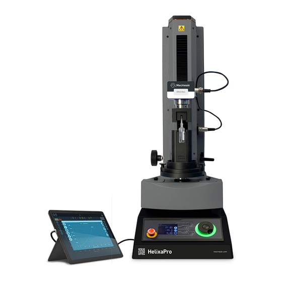
- Page 2 HelixaPro and HelixaPro Touch motorised torque tester operating manual HelixaPro precision automated torque tester, powered by VectorPro...
- Page 3 This reference manual covers the basic setup and operation of HelixaPro test stands including VectorPro software installation. All interlocked guarding for the HelixaPro is supplied as a 'PDV' (Product Design Variants). This means they will be supplied as a additional item upon special request only . Please contact your local Mecmesin sales representative or authorised distributor for more details.
- Page 4 HelixaPro and HelixaPro Touch motorised torque tester operating manual Introduction User manual icons 2.1.1 Warning 2.1.2 Caution 2.1.3 Information Customer responsibilities System summary Comms panel/ports System identification plate Unpacking and parts supplied Inspection and unpacking Packaging Moving the test stand...
- Page 5 Operating test stand without a guard fitted Operating test stand with an interlocked guard Guard closed Guard opened 9.4.1 With a test running 9.4.2 HelixaPro without VectorPro software control 9.4.3 HelixaPro with VectorPro software control Specification Dimensions Declaration of Conformity...
- Page 6 Where a test stand is used in conjunction with other machinery, it is the responsibility of the designer to ensure that all relevant directives and standards are complied with. Mecmesin test stands will confirm to all relevant directives and standards.
- Page 7 System summary HelixaPro is a motorised torque testing systems, used for torque testing of loads up to 6 N.m. 1 Height adjustable crosshead 2 Enhanced Torque Sensor (ETS) static torque transducer 3 Crosshead height adjustment dial 4 Front control panel...
- Page 8 8 USB-B port (for PC or Touch console control using VectorPro™ software) 9 Sensor 15-pin comms port System identification plate 1 Manufacturer branding 2 Model name, eg HelixaPro 3 Manufacturer address 4 Manufacturer branding 5 QR code - calibration information...
- Page 9 We strongly recommend that the packaging is retained, as this can be useful if the machine needs to be returned for calibration or shipped to another location. Parts supplied with the test stand, details the parts that should be included with your test stand. Please contact Mecmesin or your authorised distributor if any items are missing or damaged.
- Page 10 Mains power supply HelixaPro test stands can be used on 110–120 or 220–240 V AC, 50-60 Hz supplies. The rear fuse carrier is set for your local requirement but is reversible. Should you replace a fuse, ensure the correct local voltage is selected.
- Page 11 Fuse specification A HelixaPro test stand uses two 2A - Time-delay (T), 5 x 20mm fuses. If replacing a blown fuse only replace the fuse on the active side of the inlet filter with the fuse specified above, or equivalent.
- Page 12 Do not try to lift heavy loads unaided. The unpackaged weight of the test stand is listed in the specification table. The HelixaPro is supplied with rubber feet as standard or with bench securing lugs (optional). As a free-standing unit HelixaPro conforms to BS EN 61010-1:2010 section 7.4(a) requirements for stability.
- Page 13 Fitting bench securing lugs Carefully, lay the stand on its back, and fit the four rubber feet (or bench securing lugs) to the bottom of the stand as shown. Attaching the Enhanced Torque Sensor (ETS) Note: Ensure the test stand is switched off and handle lower capacity torque sensors with care, as they can be damaged by mishandling.
- Page 14 Slide the ETS down onto the dovetail bracket at the front of the crosshead. Step 3 Slide it fully downwards against the stop and tighten the securing screw using a 4mm hex key. Do not over-tighten the securing screw. Step 4...
- Page 15 Step 4 Align the electrical connector of the ETS cable with the socket on the test stand. Gently push the connector to locate, then tighten the knurled locking ring to secure it. Step 5 Align the electrical connector of the ETS cable with the socket on the sensor. Gently push the connector to locate. Step 6 Secure the ETS cable using the clip to the right of the column.
- Page 16 vertical travel of the crosshead and fasten the clip. Ensure that any grips or fixtures attached to the torque sensor do not cause excessive leverage or apply excessive axial load on the sensor. You can change ETS, disconnecting one sensor and fitting another, by reversing and repeating the steps above. Fitting the Touch console (optional) The Touch console and support arm can be fitted to the right-hand of the test stand, but it is important to ensure that any cables from the test stand to the console are clear of any moving parts, to prevent any unnecessary kinking.
- Page 17 With the T-Slot nuts aligned, insert into the T-Slot rail to the side of the test stand. It is recommended, for weight distribution, to mount the arm at the mid-point of the rail. Step 3 Tighten both upper and lower thumbscrews slowly, ensuring that the nuts have rotated one quarter-turn, for a secure grip in the rail.
- Page 18 Step 4 With the arm secured, attach the console holder back plate to the support arm console bracket using the four crosshead screws provided, then insert the Touch console. Step 5 Ensure the console holder front plate is unlocked using the key. Attach it to the back plate and then lock the front plate to secure your console.
- Page 19 The test stand will show as connected (as shown in the image to the left). 6.11 Cable management It is essential that cables are kept free of the test stand controls and any moving parts. Failure to do so could lead to personal injury or damage to the equipment.
- Page 20 One example of a lower fixture is the 100 mm diameter lower fixing plate with a diameter capacity of 20 mm to 100 mm. This is fixed to the HelixaPro drive spindle, using a 2.5 mm hex key to secure the four countersunk screws supplied.
- Page 21 A wide range of torque testing fixtures are available, including adjustable saddle plates, extended grips, mandrels, and chucks. Go to the Mecmesin website (www.mecmesin.com) or contact your local distributor for more information. 6.13 Fitting the top mass platen Step 1 Secure the top mass platen to the top of the Enhanced Torque Sensor (ETS) using the two M6 countersunk screws supplied.
- Page 22 Counterbalance mechanism The HelixaPro test stand crosshead is counterbalanced by a system of integrated weights. This enables the entire weight of the crosshead, Enhance Torque Sensor (ETS), and fixtures to be finely counterbalanced so that it does not interfere with torque measurements.
- Page 23 (1) suspended (1.5 kg in use). The right image shows the whole counterweight (1 & 2) suspended (2.25 kg in use). To adjust the counterweights in use, raise the crosshead to its highest position so that the counterweight connecting grub screw is aligned with the hole pictured above.
- Page 24 Align the counterbalance hanger vertically and secure the bolt with an 8 mm hex key. Additional weights/static masses can be suspended on the counterbalance hanger. 6.14.3 Applying top-load The top mass platen above the moving crosshead/ETS can be used in combination with the counterweights to achieve the required balance (or load) required for testing.
- Page 25 Secure the crosshead position with the securing lever to the right of the column by a half-turn clockwise. 6.15 Test stand states The test stand can be in one of five states: 1. Test readiness - Ready to start, or complete. 2.
- Page 26 Test aborted/limit triggered 7.2.2 Jog mode In jog mode, turning the wheel drives the HelixaPro clockwise or anticlockwise, corresponding to the direction of the wheel's turn. This method provides more adjustable control compared to the two fixed-speed jog control buttons (highlighted below).
- Page 27 HelixaPro test stands also include a precision jog mode: rotating the scroll wheel while holding the central scroll wheel button moves the test stand at its minimum speed. This is particularly useful when fitting specimens into grips, for example.
- Page 28 The central button is used to confirm a menu selection. It is equivalent to the tick button function. Display panel The display indicates the stand’s status, shows live values, and is used to configure the test stand's settings. The purpose of the four multi-function buttons is indicated on-screen by adjacent icons. Below is an image illustrating a typical example of the on-screen icons corresponding to the physical buttons.
- Page 29 7.4.3 Pause/Stopped Icon Action Continue test sequence. Stop test - Shown when the Pause button is pressed. This ends the test at this point. Move to the home position (start position from the beginning of the previous test) -This icon is only visible after pressing the 'Stop' button.
- Page 30 For example: A HelixaPro stand fitted with a 6 N.m torque sensor must reach 1.5 N.m in either direction before the timeout activation is applied. Loads below the 25% limit will not activate the timeout and the stand will actively hold the load applied.
- Page 31 Example ° 1. Clockwise Angle: +1000 ° 2. Anticlockwise Angle -30 3. Initial stroke: Clockwise 4. Move to Start: Yes ° ° Unless already at -30 the spindle will first travel to that point. The stand will then move to +1000 from tared zero, followed °...
- Page 32 Please note once this has been set you cannot access the menu without the PIN, so it is crucial that you keep a record of this safe. If a PIN code has been set and then lost or forgotten, please contact Mecmesin technical support or your local distributor.
- Page 33 not connect the test stand until the installation has been completed. Step 1 VectorPro software installation Locate the download or installation folder and start the installation by double-clicking the Vector.Installer.exe (executable file). Step 2 VectorPro software installation Once open, click on the ' I nstall VectorPro' option. Step 3 VectorPro software installation The VectorPro installer will install drivers necessary to complete the installation.
- Page 34 VectorPro software installation Once the associated drivers have been installed, the VectorPro software installation wizard will launch. Click ' Next' to continue and review the software license agreement. Step 5 VectorPro software installation Before continuing the software installation, it is important that you read, understand and agree to the software license agreement in full.
- Page 35 VectorPro software installation Select the installation location and whether the software installs for all users (Everyone) on this computer or the current user only (Just me). Press 'Next' to continue. Step 7 VectorPro software installation Click 'Next' to confirm installation. Step 8 VectorPro software installation After installation click ' C lose'.
- Page 36 VectorPro software installation Click the 'Tick' button to continue. Step 10 VectorPro software installation You can now choose whether to enable ' F ull Screen Mode' for VectorPro. Step 11 VectorPro software installation Finally click the ' O ff' button to exit the installer.
- Page 37 Default database location: C:\ProgramData\Mecmesin\VectorPro\ Default install location: C:\Program Files (x86)\Mecmesin\VectorPro\ Custom database location: If a custom database location is specified, the Windows user must also have Admin access for this location If you are unsure of how to perform any of the steps above, please contact your organisation's IT department for assistance.
- Page 38 All HelixaPro test stands are supplied with 'Interlock enabled', this means they are electrically and mechanically ready to use with a Mecmesin supplied guarding system. Interlocked guarding for the HelixaPro is supplied as a Product Design Variant (PDV), available as an additional item upon request.
- Page 39 'Interlock' connection, in place of the removed override plug. When a guard is fitted and connected to the HelixaPro there is no need for any menu updates or user interaction to make it functional. The stand will have certain operations and user status warnings when the guard is opened and closed.
- Page 41 ** With upper and lower mounting tables fitted Please note that the specifications and features described in this manual are subject to change without notice. Mecmesin reserves the right to make improvements or modifications to the product at any time, which may not be reflected in this...
- Page 42 Dimensions Front view: Side view: Rear view:...
- Page 43 Note: HelixaPro dimensions are approximate and in millimeters (mm).
- Page 44 Declaration of Conformity For the full declaration of conformity certificate for the HelixaPro, click here. Original instructions published in English language. © PPT Group UK Ltd t/a Mecmesin Contact us +44 (0)1403 799979 info@mecmesin.com...
- Page 45 Newton House Spring Copse Business Park Slinfold, West Sussex RH13 0SZ United Kingdom PPT Group UK Ltd is a company registered in England and Wales, company number 414668. Mecmesin is a PPT Group brand Source URL (modified on 30/07/2024 - 17:53):https://help.mecmesin.com/docs/helixapro-motorised-torque-tester-operating-manual...
Need help?
Do you have a question about the HelixaPro and is the answer not in the manual?
Questions and answers