
Subscribe to Our Youtube Channel
Related Manuals for Mecmesin VortexPro


Summary of Contents for Mecmesin VortexPro
- Page 1 Published on Mecmesin Support (https://help.mecmesin.com) Home > VortexPro Motorised Torque Tester Operating Manual Support Product VortexPro Support Software VectorPro Revision ID 13123 Manual 431-483...
- Page 2 VortexPro and VortexPro Touch motorised torque tester operating manual VortexPro automated torque tester, powered by VectorPro...
- Page 3 Safe Use of Mains Powered Test Systems Systems’ before attempting to operate your VortexPro Test System. This reference manual covers the basic setup and operation of VortexPro test stands including VectorPro software installation. All interlocked guarding for the VortexPro is supplied as a 'PDV' (Product Design Product Design Variants).
- Page 4 VortexPro and VortexPro Touch motorised torque tester operating manual Introduction User manual icons 2.1.1 Warning 2.1.2 Caution 2.1.3 Information Customer responsibilities System summary Comms panel/ports System identification plate Unpacking and parts supplied Inspection and unpacking Packaging Moving the test stand...
- Page 5 Operating test stand without a guard fitted Operating test stand with an interlocked guard Guard closed Guard opened 9.4.1 With a test running 9.4.2 VortexPro without VectorPro software control 9.4.3 VortexPro with VectorPro software control Specification Dimensions Declaration of Conformity...
-
Page 6: Customer Responsibilities
Where a test stand is used in conjunction with other machinery, it is the responsibility of the designer to ensure that all relevant directives and standards are complied with. Mecmesin test stands will confirm to all relevant directives and standards. -
Page 7: System Summary
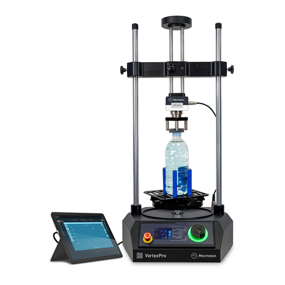
System summary VortexPro is a motorised torque testing systems, used for torque testing of loads up to 10 N.m. 1 1 Height adjustable crosshead 2 2 Enhanced Torque Sensor (ETS) static torque transducer 3 3 Front control panel 4 4 Emergency stop button... - Page 8 1 Manufacturer branding 2 Model name, eg VortexPro 3 Manufacturer address 4 Manufacturer branding 5 QR code - calibration information 6 Serial number, eg 24-1005-03 7 Voltage information 8 Conformity markings...
- Page 9 Important! supplier immediately who will decide the most appropriate action and rectify the situation as quickly as possible. Before installing or operating the VortexPro system ensure that no visible damage has occurred during the shipping of the device Packaging We strongly recommend that the packaging is retained, as this can be useful if the machine needs to be returned for calibration or shipped to another location.
-
Page 10: Initial Setup
Mains power supply VortexPro test stands can be used on 110–120 or 220–240 V AC, 50-60 Hz supplies. The rear fuse carrier is set for your local requirement but is reversible. Should you replace a fuse, ensure the correct local voltage is selected. -
Page 11: Fuse Specification
Fuse specification A VortexPro test stand uses two 2A - Time-delay (T), 5 x 20mm fuses. If replacing a blown fuse only replace the fuse on the active side of the inlet filter with the fuse specified above, or equivalent. - Page 12 Hex key to loosen the retention screws. Step 1 VortexPro - Slide console bracket down the desired column To fit the Touch console support arm, slide the support arm bracket down the column. Depending on the required height and clearance for your application, you may need to remove the crosshead first..
- Page 13 Step 2 VortexPro - Tighten screws in console column bracket Pass the screws through the bracket and secure them using a 4 mm Hex key. It's recommended to have assistance during this step to support the bracket in the desired position.
-
Page 14: Cable Management
Ensure the console holder front plate is unlocked using the key. Attach it to the back plate and then lock the front plate to secure your console. Adjust the angle of the arm and the orientation of the console as needed. Finally, tighten each hex screw on the support arm joints and ball-joint to secure the desired position. - Page 15 The most commonly-used lower fixture is the 188 mm diameter lower fixing plate with a diameter capacity of 10 mm to 190 mm. This is fixed to the VortexPro drive spindle, using a 2.5 mm Hex key to secure the four...
-
Page 16: Test Stand States
A wide range of torque testing fixtures are available, including adjustable saddle plates, extended grips, mandrels, and chucks. Go to the Mecmesin website (www.mecmesin.com) or contact your local distributor for more information. 6.10 Test stand states The test stand can be in one of five states: 1. -
Page 17: Front Panel Controls
Static Test aborted/limit triggered 7.2.2 Jog mode In jog mode, turning the wheel drives the VortexPro clockwise or anticlockwise, corresponding to the direction of the wheel's turn. This method provides more adjustable control compared to the two fixed-speed jog control... -
Page 18: Navigation And Selection
VortexPro test stands also include a precision jog mode: rotating the scroll wheel while holding the central scroll wheel button moves the test stand at its minimum speed. This is particularly useful when fitting specimens into grips, for example. -
Page 19: Display Panel
7.2.4 Central button The central button is used to confirm a menu selection. It is equivalent to the tick button function. Display panel The display indicates the stand’s status, shows live values, and is used to configure the test stand's settings. The purpose of the four multi-function buttons is indicated on-screen by adjacent icons. -
Page 20: Settings Menu
Emergency stop button pushed: Message: ‘Emergency Stop!!! Emergency stop button pushed: Message: Emergency Stop!!!’. Release the emergency stop to regain control and remedy the situation before resuming testing. Note there is no on-screen icon for the emergency stop. 7.4.3 Pause/Stopped Icon Icon Action... -
Page 21: Jog Settings
For example: A VortexPro stand fitted with a 6 N.m torque sensor must reach 1.5 N.m in either direction before the timeout activation is applied. Loads below the 25% limit will not activate the timeout and the stand will actively hold the load applied. -
Page 22: Half Cycle
Setting Setting Options Options Start direction Choose whether the test direction is clockwise or anticlockwise Move to start Select if the test moves to the start position first Example Example ° 1. Clockwise Angle: Clockwise Angle: +1000 ° 2. Anticlockwise Angle Anticlockwise Angle -30 3. - Page 23 Languages Select your desired language. Upon confirmation, you are returned to the settings menu in the language chosen. Information This screen is used to display vital information relating to your VortexPro and the connected ETS sensor including...
-
Page 24: Software Setup
You can also review calibration data for the test system. Software setup A VectorPro license is required to run a VortexPro test stand and VectorPro software. VectorPro test software is supplied on a USB key or can be downloaded online from: https://downloads.vectorpro.cloud... - Page 25 Step 4 VectorPro software installation Once the associated drivers have been installed, the VectorPro software installation wizard will launch. Click 'Next Next' to continue and review the software license agreement. Step 5 VectorPro software installation Before continuing the software installation, it is important that you read, understand and agree to the software license agreement in full.
- Page 26 VectorPro software installation Select the installation location and whether the software installs for all users (Everyone) on this computer or the current user only (Just me). Press 'Next Next' to continue. Step 7 VectorPro software installation Click 'Next Next' to confirm installation. Step 8...
- Page 27 VectorPro software installation After installation click 'Close Close'. Step 9 VectorPro software installation Click the 'Tick Tick' button to continue. Step 10 VectorPro software installation You can now choose whether to enable 'Full Screen Mode Full Screen Mode ' for VectorPro. Step 11...
- Page 28 Default database location: C:\ProgramData\Mecmesin\VectorPro\ Default install location: Default install location: C:\Program Files (x86)\Mecmesin\VectorPro\ Custom database location: Custom database location: If a custom database location is specified, the Windows user must also have Admin access for this location If you are unsure of how to perform any of the steps above, please contact your organisation's IT department for...
- Page 29 VortexPro test stands can be operated without a supplied guard for applications that do not warrant a guard. Test stands have an 'Override Override' feature that allows an interlock override plug (Part no.
- Page 30 Interlock' connection, in place of the removed override plug. When a guard is fitted and connected to the VortexPro there is no need for any menu updates or user interaction to make it functional. The stand will have certain operations and user status warnings when the guard is opened and closed.
-
Page 32: Specification
Specification VortexPro VortexPro 0 - 10.0 Test stand rated Test stand rated kgf.cm 0 - 100 capacity capacity lbf.in 0 - 90 0 - 0.3 0 - 1 0 - 1.5 0 - 3.0 0 - 6.0 0 - 10.0... - Page 33 Dimensions Front view: VortexPro - Diagram/dimensions (Front) Side view:...
- Page 34 VortexPro - Diagram/dimensions (Side) Top-down view: VortexPro - Diagram/dimensions (Top) Note: VortexPro dimensions are approximate and in millimeters (mm). Note:...
-
Page 35: Declaration Of Conformity
Declaration of Conformity For the full declaration of conformity certificate for the VortexPro, click click here here. . Original instructions published in English language. © PPT Group UK Ltd t/a Mecmesin Contact us +44 (0)1403 799979 info@mecmesin.com PPT Group UK Ltd... - Page 36 Slinfold, West Sussex RH13 0SZ United Kingdom PPT Group UK Ltd is a company registered in England and Wales, company number 414668. Mecmesin is a PPT Group brand Source URL (modified on 24/06/2024 - Source URL (modified on 24/06/2024 - 09:28):...
Need help?
Do you have a question about the VortexPro and is the answer not in the manual?
Questions and answers