
Subscribe to Our Youtube Channel
Related Manuals for Mecmesin OmniTest 10


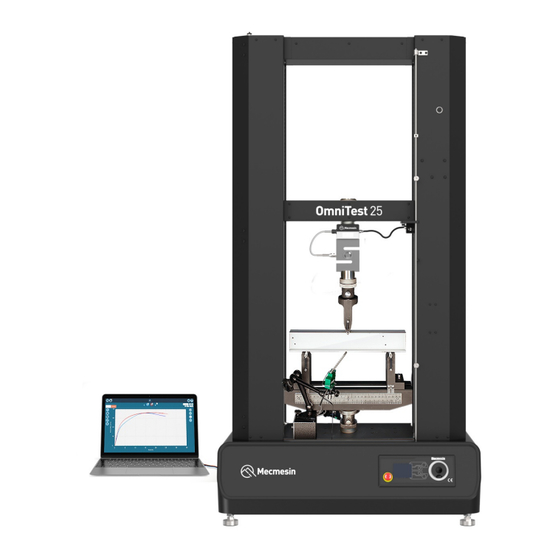
Summary of Contents for Mecmesin OmniTest 10
- Page 1 Published on Mecmesin Support (https://help.mecmesin.com) Home > OmniTest 10/25/50 Twin Column Installation and Operation Manual Support Product OmniTest Support Software VectorPro Revision ID 13156 Manual 431-965...
- Page 2 OmniTest 10/25/50 twin column test system user manual...
- Page 3 This reference manual covers the operation of an OmniTest Twin Column force test stand (Mk1 and Mk2), intended for use with Mecmesin enhanced load sensors (ELS), extensometer devices and other Mecmesin accessories. Operation of additional accessories is covered in separate documentation.
- Page 4 Important It is essential that you familiarise yourself with the contents of this Manual and the separate Guide to Safe Use of Mains Powered Test Stands (Part: 431-398) before attempting to operate your OmniTest twin column test stand. User manual icons Throughout this manual, the icons shown below are used to identify important health and safety information as well as additional installation/operation guidance.
- Page 5 OmniTest 10/25/50 twin column test system user manual Scope Important User manual icons 3.1.1 Warning 3.1.2 Caution 3.1.3 Information Items supplied with your test stand Accessories available OmniTest Twin Column System Diagram Front View Side View Initial setup Unpacking the Stand...
- Page 6 10.2 PIN code 10.3 Pre-load threshold 10.4 Information Connectors Panel Specification 12.1 OmniTest 10/25/50 Mk1 (Blue) 12.2 OmniTest 10/25/50 Mk2 (Black) OmniTest twin column dimensions 13.1 OmniTest 10/25/50 Mk1 (Blue) 13.2 OmniTest 10/25/50 Mk2 (Black) 13.2.1 OmniTest 10/25 Mk2 (Black) 13.2.2...
-
Page 7: Items Supplied With Your Test Stand
(www.mecmesin.com/distributors). For connection of the stand to your computer system a Mecmesin supplied 2m USB B to USB A cable communications cable is required (Part: 351-093). Here you can see some of the grips and fixtures that are available. -
Page 8: Front View
OmniTest Twin Column System Diagram Front View 1 ELS loadcell mounted through crosshead 2 Upper QC mounting adaptor (QC20 'type C', or QC32 'type L') 3 Lower QC mounting adaptor (QC20 'type C', or QC32 'type L') 4 Upper adjustable safety limit switch 5 Lower adjustable safety limit switch 6 Multi-function scroll wheel and menu selection button 7 Emergency stop button... - Page 9 ELS loadcell connection to OmniTest Connectors panel Mains input socket and power switch Interlock port (OmniTest 10/25/50 Mk2 (Black))
-
Page 10: Initial Setup
Suitable lifting equipment must be used in conjunction with the test stands lifting points. Environment Conditions In line with BS EN 61010-1 it is recommended that your Mecmesin OmniTest Twin Column test stand is operated in an environment that matches the following conditions:... - Page 11 Mains power supply: OmniTest 10/25/50 Mk2 (Black) The OmniTest 10/25/50 Mk2 (Black) test stand requires a 220-240 V AC power supply . Regions with a 110-120 V AC mains power supply must use the supplied external transformer (Part: 164-366). The fuse housing must be set to 220-240 V AC, as supplied Please consult a qualified electrician if you are unsure of your mains power supply/out.
- Page 12 Mains power supply: OmniTest 10/25/50 Mk1 (Blue) The OmniTest 10/25/50 Mk1 (Blue) test stands can be used on 110–120 and 220–240 V AC 50-60 Hz supplies. The rear fuse carrier will be set for your local requirement but is reversible, so should you replace a fuse, the correct local voltage must be selected.
- Page 13 The image above shows a selection of Enhanced Load Sensors (ELS). Some ELS devices shown may not be compatible with twin column test stands. Contact Mecmesin technical support or your local Mecmesin distributor for further information. Attaching the ELS to your test stand 7.4.1...
- Page 14 Securing the loadcell with the central M18 bolt Important Ensure that attached grips and fixtures do not overload the ELS. If in doubt, please check the weight of any addition grips and fixtures prior to fitting these. 7.4.2 ELS-P 50 kN pancake loadcell Important The ELS-P 50 kN pancake loadcell uses an additional method of attachment that should be performed first.
- Page 15 7.5.1 OmniTest 10/25/50 Mk1 (Blue) To connect your ELS to your OmniTest stand simply plug the Mecmesin ELS to OmniTest cable (Part: 352-275-V01) into both the load cell and the ELS shroud located on the back of the stand. Connecting the ELS to the test stand.
- Page 16 As enhanced load sensors are ‘smart’ devices all calibration and capacity information is passed to the stand automatically as the sensor is connected. Connecting the OmniTest twin column to a PC or console Important VectorPro software must be installed on the assigned PC (or console) before connecting the test stand to that...
-
Page 17: Cable Management
Mecmesin developed the Vector Instrument Programmer (VIP) to simplify the process of updating your Vector-based test stand or instrument. For example, to update your OmniTest test stand to the latest firmware, download the VIP application and ensure the PC that your OmniTest is connected to also has an active internet connection. - Page 18 Vector Instrument Programmer (VIP) is self updating so the installation only needs to be completed once. Updates to VIP are pushed to the app when available. The app does not automatically create a desktop shortcut. To create a shortcut, locate the VIP executable file at the following location on your PC: C:\Program Files (x86)\PPT Group\Vector Instrument Programmer\VectorInstrumentProgrammer.exe 7.8.2...
-
Page 19: Attaching Grips And Fixtures
Important: Do not disconnect the device during an update. Software updates will be published when updates are released in the software section of our support center at www.Mecmesin.com. If you are unsure or if you need help updating your product please contact support@mecmesin.com. Attaching grips and fixtures Ensure that the OmniTest test stand is not in Jog Mode when attaching accessories. - Page 20 The OmniTest twin column test stand features a base plate with numerous threaded holes, spread symmetrically across its width, as well as fixing points for a standard 20 mm QC adapter. This configuration supports the flexible attachment of a wide variety of accessories.
-
Page 21: Setting The Limit Stops
Mecmesin LTE-1100 extensometers are available and can be fitted directly to the base plate (above). 7.10 Setting the Limit Stops Limit Stops help prevent damage to load cells and fixtures by stopping the crosshead movement before the moving fixtures come into contact with static parts of the stand. Their positions are adjusted after the fitting of fixtures and test samples. -
Page 22: Test Stand States
Limit stops on an OmniTest twin column 7.11 Test stand states The test stand can be in one of five states: 1. Test readiness - ready to start, or complete 2. Testing – test operation sequence is running 3. Stopped - test interrupted or emergency stop pressed 4. -
Page 23: Front Panel Controls
Front panel controls Status messages 2Button functions Multi-Function selector buttons 4Multi-function scroll wheel 5Scroll wheel button 6Emergency stop button Display 8LED indication dial Emergency Stop button Push the emergency stop button to immediately stop the crosshead movement. Rotate the button to release it and resume crosshead control. - Page 24 Amber Light Static: The current test has completed Rotating: The crosshead is moving Red Light Static: The test has stopped or a limit has been triggered 8.2.2 Jog mode When in jog mode the scroll wheel drives the crosshead directly up (clockwise) or down (anticlockwise). This offers more variable control when compared to the two fixed speed jog control buttons (circled in red below).
-
Page 25: Display Panel
selections and their values. This is an alternate navigational option to using the up and down arrow buttons. 8.2.4 Central button The central button is used to confirm a menu selection. It is equivalent to the tick button. It can also be used to activate fine jog control. Use by rotating the scroll wheel while holding the central scroll button. This drives the test stand at its minimum speed. -
Page 26: On-Screen Icons
1. Pre-Test - ready to start, or complete, 2. Testing – test operation sequence is running, 3. Test Stop- test interrupted or emergency stop pressed, 4. Jog Mode - for jogging or positioning the crosshead manually, 5. Settings Menu – for adjusting the test stand settings, In each state, the selector buttons have functions described by the on-screen icons. - Page 27 Icon Action Crosshead has reached a lower limit (load signal from a connected gauge, set to Stop, or a limit switch) and stopped Exit jog mode 8.5.4 D: Settings Menu Icon Action Confirm selection (or press the scroll wheel button) Navigate ‘up’...
-
Page 28: Automatic Els Firmware Update
Automatic ELS firmware update All OmniTest twin column test stands with firmware 3.1.0.0 and above have the ability to update the firmware of any connected ELS device. This feature is seamlessly managed through the front panel and ensures that the latest firmware is on the ELS devices. Step 1 Connect the ELS device To start the update connect the ELS to the test stand and switch the test stand on. - Page 29 If more than one ELS is connected (load cell and a short analogue extensometer) the additional devices will be listed. To start the update of the first ELS device press the ‘tick’ icon. Please note If you press the ‘Cross’ icon the upgrade can be started manually by opening the information screen located within the settings menu and scrolling to the ELS firmware version.
-
Page 30: Jog Settings
Please note once this has been set you cannot access the menu within the PIN, so it is crucial that you keep a record of this safe. To remove a PIN code, set the four-digit number to '0000'. If a PIN code has been set and then lost or forgotten, please contact Mecmesin technical support or your local distributor. 10.3 Pre-load threshold This menu displays the pre-load threshold as configured by VectorPro™, changes here will be overwritten by VectorPro next... -
Page 31: Connectors Panel
Connectors Panel 1. Extensometer port 2. Digital IO port (not currently implemented) 3. Calibration date and serial number 4. Interlock override switch 5. Interlock port 6. USB-B Comms port 7. ELS 2 and 3 (not currently implemented) -
Page 32: Specification
Specification 12.1 OmniTest 10/25/50 Mk1 (Blue) OmniTest Test Stand Rated Capacity kN 1000 2500 5000 2200 5500 11000 Number of Ballscrews Class 0.5, according to the requirements of BS EN ISO7500 (requires optional onsite UKAS System accuracy accredited system calibration) - Page 34 OmniTest twin column dimensions 13.1 OmniTest 10/25/50 Mk1 (Blue) 13.2 OmniTest 10/25/50 Mk2 (Black) 13.2.1 OmniTest 10/25 Mk2 (Black)
- Page 35 13.2.2 OmniTest 50 Mk2 (Black)
-
Page 36: Declarations Of Conformity
Declarations of Conformity Original instructions published in English language. © PPT Group UK Ltd t/a Mecmesin Contact us +44 (0)1403 799979 info@mecmesin.com PPT Group UK Ltd t/a Mecmesin Newton House Spring Copse Business Park Slinfold, West Sussex RH13 0SZ United Kingdom PPT Group UK Ltd is a company registered in England and Wales, company number 414668.
Need help?
Do you have a question about the OmniTest 10 and is the answer not in the manual?
Questions and answers