
Subscribe to Our Youtube Channel
Related Manuals for Mecmesin Tornado


Summary of Contents for Mecmesin Tornado
- Page 1 Tornado digital torque tester Operating Manual S.I. Instruments 256 South Rd. Hilton South Australia 5033 Ph (08) 8352 5511 info@si-instruments.com.au www.si-instruments.com.au...
-
Page 2: Table Of Contents
Contents The Tornado Assembly of the Tornado Powering the Tornado Using the Tornado Basic Functions Advanced Menu Options RS232 Commands Advanced Menu Options Flowcharts Dimensions Tornado Specifications page 1... - Page 3 To configure the advanced features of the Tornado, a full menu-driven system is accessible using the keys identified on the front panel with blue text - see page 11, Advanced Menu Options.
-
Page 4: Assembly Of The Tornado
Align the top plate with the torque drive so that the handle is on the left-hand When Tornado is in transit, the top side of the top plate. Using the 2.5mm Allen key (provided), plate is removed to avoid damage tighten the four socket countersunk screws hand tight. - Page 5 Align the top plate with the torque drive so that the handle is on the left-hand When Tornado is in transit, the top side of the top plate. Using the 2.5mm Allen key (provided), plate is removed to avoid damage tighten the four socket countersunk screws hand tight.
-
Page 6: Powering The Tornado
Powering the Tornado The Tornado is supplied with a set of 5 Nickel Metal Hydride AAA rechargeable batteries, which are supplied fully charged to allow use straight from the box. Do not use any other battery charger other than that supplied with the torque tester. -
Page 7: Using The Tornado
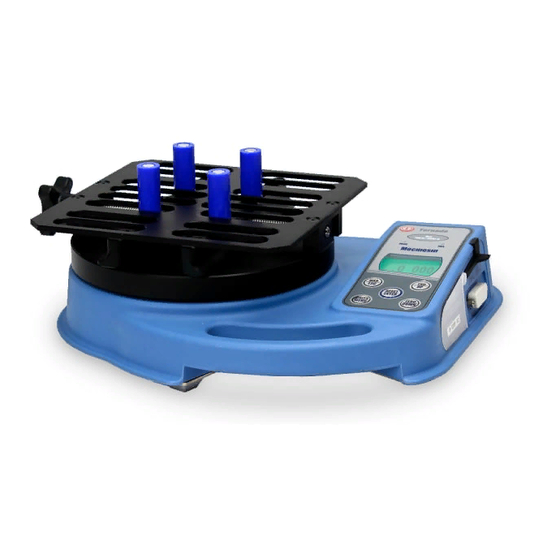
Using the Tornado The Tornado is supplied with 4 pegs which grip the sample Fitting accessories during testing. Screw the pegs into the runners on the top fixture equally spaced to ensure the sample is securely gripped when the When using the Tornado 1.5N.m,... -
Page 8: Basic Functions
OL symbol will appear permanently on the display. Consult your supplier to arrange repair. To power down the Tornado press the red key. Basic Functions Clockwise torque is displayed on the Tornado and recognised by the symbol shown in Fig. - Page 9 When applying counter-clockwise torque, the indicator bar begins striped, then becomes solid (see Fig. 4b & 4c). During operation of the Tornado it is sometimes necessary Zeroing the Tornado to zero the display - e.g. when you wish to tare out a displayed torque applied by the sample, so it does not become part of the measured reading.
- Page 10 Dual max Fig. 4a Max clockwise reading Direction of torque Max counter- currently clockwise reading applied Torque currently applied Press the MAX key again and the display will show the Max clockwise torque maximum clockwise torque identified by its symbol. Fig.
- Page 11 Please note that the continuous data output only starts connected, the display will when the load threshold default of 2% of the rated capacity periodically freeze. of the Tornado is reached. This threshold can be set from 0-100% (see page 24). page 10...
-
Page 12: Advanced Menu Options
* Note that the continuous transmission mode cannot be entered via this method. Advanced Menu Options The Tornado Advanced Menus are navigated using the blue text on the function keys. Navigating the menus Press and hold the MENU key for approximately 3 seconds to access page 1 of the main-menu, (see Fig. - Page 13 ALARM The Tornado has an audible and visual pass/fail alarm feature. A band of acceptable torque result values can be appointed, and the alarm set to trigger when recorded values fall outside of, or within this band. Alarms will not trigger in the first 1% of full-scale use.
- Page 14 ALARM sub-menu 3 The display will now show the two limits - LIMIT 1 (lower limit) and LIMIT 2 (upper limit) - plus the value they are set to (ALARM LIMITS) and whether they are in a clockwise (CW) or counter-clockwise (CCW) direction.
- Page 15 The display shows OUT BAND and IN BAND. This menu ALARM sub-menu 5 selects which values are to be considered. (ALARM BAND) OUT BAND Any value falling outside the set limits LIMIT 1 and LIMIT 2. IN BAND Any value falling between the set limits LIMIT 1 and LIMIT 2.
- Page 16 Controller) pages 47-48 for details of the signal. To configure the signal output of the Tornado, press and hold the MENU key until page 1 of the main menu appears. Press the DOWN key to move the arrow cursor to PLC and press ENTER.
- Page 17 The display will show STATE: AT ALARM sub-menu 1 HIGH Will set PLC signal high at Tornado's alarm. Will set PLC signal low at Tornado's alarm. Select the desired function and press the ENTER key. The display will revert back to PLC sub-menu 1 and PLC ON will now be displayed.
- Page 18 PASSWORD Once the desired settings for the Tornado have been established, it is possible to password protect the menu pages, so that no further changes may be made without authorised access. To access the PASSWORD function, press and hold the MENU key until page 1 of the main-menu appears.
- Page 19 Fig. 9 For illustration only The % drop feature is based on the capacity of the Tornado unit, and refers to the amount that the 1st peak to be calculated must drop before the software starts to look for the 2nd peak.
- Page 20 TXD key on a dual max screen must (TX PEAKS) now be selected. The following display will appear. TX 1st PEAK Sets the Tornado to transmit the slip torque (1st peak) only. TX 2nd PEAK Sets the Tornado to transmit the bridge torque (2nd peak) only.
- Page 21 AV/TIME x Peak 4N.m Average 3N.m Start Threshold Stop Threshold 2N.m 1N.m TIME This function allows the average load reading to be The maximum duration of AV/TIME displayed. The average starts being calculated when the calculation is approx. 22 minutes. START threshold (% of full-scale) is reached and stops being calculated when the load passes through the STOP threshold.
- Page 22 The maximum duration of AV/TIME calculation is approx. 22 minutes. When the time limit expires, ‘AT’ is displayed in the main display, and the MAX key must be pressed in order to clear ‘AT’ and continue use of the Tornado. MAIN MENU PAGE 2 Fig. 11...
- Page 23 Tornado into test or production systems. Note: A footswitch assigned to the UNITS key can allow entry into the menu page, but the Tornado will not respond to further footswitch operations from either footswitch 1 or 2 once in the menu.
- Page 24 Communications settings are selected to configure interfacing of the Tornado with peripheral devices. The menu is also used to configure the storage settings of the Tornado, which may store up to 500 readings in its on-board memory. To access the COMMS settings, press and hold the MENU key until page 1 of the main menu appears.
- Page 25 The transmission (or Baud) rate can now be set. PORT sub-menu 3 Use the UP or DOWN key to position the arrow cursor at (BAUD RATE) the relevant speed (9600, 19200, 57600 or 115200). Press ENTER to select. Additional characters can be appended to the transmitted PORT sub-menu 4 load (RS232 only).
- Page 26 To set SEND MEM, move the arrow cursor against it in SEND FROM MEMORY COMMS sub-menu 1 and press the ENTER key. This will cause a TX symbol to flash in the main display as the memory data is now transmitted to a peripheral device. The data is transmitted at the settings defined by PORT.
- Page 27 – consult your Place the Tornado on a flat level surface. Press and hold the supplier. MENU key until page 1 of the main-menu appears. Press and release the MENU key to access the main menu page 2.
- Page 28 If the offset is between 5 - 10 %, please contact your supplier to arrange a re-calibration of your Tornado. If the offset is greater than 10 %, please contact your supplier to arrange for a possible torque sensor replacement.
- Page 29 MAX LOCK Once the desired Max display mode has been selected, it is possible to lock the mode, so that further pressing the MAX key results in no change. To access the MAX LOCK function, press and hold the MENU key until page 1 of the main-menu appears. Press and release the MENU key twice to access the main menu page 3.
- Page 30 It is possible to activate a backlight on the Tornado display. BACKLIGHT To access the BACKLIGHT function, press and hold the MENU key until page 1 of the main-menu appears. Press and release the MENU key twice to access the main menu page 3.
- Page 31 ESC key to return to the main display. DEFAULTS To restore the factory default settings of your Tornado, press and hold the MENU key until page 1 of the main-menu appears. Press and release the MENU key twice to access the main menu page 3.
- Page 32 Factory Default Settings Menu Function Default Setting ALARM PASSWORD FREEZE % TAMP EV AV TIME RATE MEDIUM FOOTSWITCH1 FOOTSWITCH2 COMMS P,OFF,ON,9600,CL,0,2,S PORT SELECTED UNITS OFF SIGN ON BAUD 9600 TERMINAL CR AND LF LINE DELAY 0 SECONDS TX THRESHOLD 2% TX METHOD RS232 MAX LOCK UNITS LOCK...
-
Page 33: Rs232 Commands
RS232 Commands Table: Configuration It is possible to remotely read/configure the settings of your Tornado by sending the following RS232 command characters: Decimal Hexadecimal Function Character in ASCII 0x4D Current mode 0x55 Current units 0x43 Torque sensor capacity 0x40 Configuration status request... - Page 34 RS232 Command Responses: Information It is possible to remotely interrogate your Tornado by sending the following RS232 commands. This will inform you which settings are currently configured. Command: M Response Tornado Display Mode Normal Normal Mode MaxC Max Counter-clockwise MaxT...
- Page 35 Command: @ When all options are OFF, and the Tornado is set at defaults, you will receive the following information listing: RESPONSE EXPLANATION OF RESPONSE Tornado Gauge type 10.000 Torque sensor size in N.m as per transmitting 'C' Version number...
- Page 36 When all options are ON, you will receive the following information listing for each option: ALARM ON options explained below: ALARM ON,1,2,3,4,5,6,7 Alarm Number Selected; 1, 2, 3, 4 or 5 x Limit1 value x Limit2 value B = Buzzer, L = LED, BL = Buzzer & LED O = Out of Band, I = In Band P = Pass, F = Fail C = Continuous, P = Pulse, or blank...
- Page 37 AV TIME ON options explained below: AV TIME ON,1,2 Start Threshold value Stop Threshold value RATE 1 ON options explained below: RATE 1 M = Medium, H = High FOOTSWITCH1 ON options explained below: FOOTSWITCH1 ON,1 Footswitch 1 - M = Max, U = Units, T = Txd, Z = Zero, R = Reset FOOTSWITCH2 ON options explained below: FOOTSWITCH2 ON,1 Footswitch 2 - M = Max, U = Units, T = Txd, Z = Zero, R = Reset...
- Page 38 MAX LOCK 1 options explained below: MAX LOCK 1 Max key locked, ON or OFF UNIT LOCK 1 options explained below: UNITS LOCK 1 Units key locked, ON or OFF BACKLIGHT 1 options explained below: BACKLIGHT 1 Backlight enabled, ON or OFF AUTO-OFF 1 options explained below: AUTO-OFF 1 Auto-off time, OFF, 5 mins or 10 mins...
-
Page 39: Advanced Menu Options Flowcharts
Advanced Menu Options Flow Chart Menu Page 1 On the following pages are flowcharts to help you navigate the menus found in the Tornado. They appear in the order they appear on the three pages of the main menu on the instrument. - Page 40 Advanced Menu Options Flow Chart Menu Page 1 press press ENTER PLC OUTPUT RESET 12.75 ALARM CONTINUOUS PASSWORD press press ENTER ENTER FREEZE press ENTER AT LIMITS PULSE % TAMP EV press AVERAGE/TIME ENTER AT ALARM Page 1 STATE HIGH press ENTER PASSWORD...
- Page 41 Advanced Menu Options Flow Chart Menu Page 1 FREEZE press FREEZE DISP ALARM PASSWORD press press ENTER ENTER FREEZE % TAMP EV AVERAGE/TIME HIGH Page 1 % TAMP EV press % DROP SET % TX 1st PEAK ALARM TX 2nd PEAK PASSWORD FREEZE press...
- Page 42 Advanced Menu Options Flow Chart Menu Page 2 RATE press RATE RATE FOOTSWITCH1 press ENTER MEDIUM FOOTSWITCH2 COMMS HIGH INFORMATION press ENTER CALIBRATION Page 2 FOOTSWITCH1 press press ENTER RATE FOOTSWITCH1 FOOTSWITCH1 press ENTER FOOTSWITCH2 COMMS UNITS INFORMATION CALIBRATION ZERO RESET Page 2 FOOTSWITCH2...
- Page 43 Advanced Menu Options Flow Chart Menu Page 2 COMMS RS232 TX THRESHOLD LINE DELAY NULL press ENTER press ENTER DIGIMATIC SET % SECONDS : press ENTER DUAL CR LF press ENTER RATE PORT TX UNITS TX SIGN 9600 press press ENTER ENTER press...
- Page 44 Advanced Menu Options Flow Chart Menu Page 3 MAX LOCK press MAX LOCK MAX LOCK UNITS LOCK press press ENTER ENTER BACKLIGHT AUTO OFF INVERT DEFAULTS Page 3 UNITS LOCK press MAX LOCK UNITS LOCK UNITS LOCK press press ENTER ENTER BACKLIGHT AUTO OFF...
- Page 45 Advanced Menu Options Flow Chart Menu Page 3 INVERT press INVERT DISP MAX LOCK UNITS LOCK press ENTER press ENTER BACKLIGHT AUTO OFF INVERT DEFAULTS Page 3 DEFAULTS press press MAX LOCK DEFAULTS RESTORE UNITS LOCK press ENTER press ENTER press ENTER BACKLIGHT...
-
Page 46: Dimensions
DIMENSIONS Side view page 45... - Page 47 Top view 303 mm *Min-Max opening: 10 - 190 mm diameter - Tornado 10N.m & 6N.m 10 - 78 mm diameter - Tornado 3N.m & 1.5N.m page 46...
-
Page 48: Tornado Specifications
TORNADO SPECIFICATIONS RANGE & RESOLUTION ACCURACY Capacity (N.m) N.cm mN.m 1.5 x 0.0005 150 x 0.05 1500 x 0.5 3.0 x 0.001 300 x 0.1 3000 x 1 6.0 x 0.002 600 x 0.2 6000 x 2 10 x 0.002 1000 x 0.2... - Page 49 The relay is powered from a 5V regulator inside the Tornado. Supply voltage: The relay state is controlled via a TTL signal from the Tornado and Input control: is in a 'closed position' when a logic '1' input is applied.
- Page 50 Communications Cables Interface cables for connecting your Tornado to peripheral devices: Mecmesin Cable Part Number Tornado to RS232 (9-pin D-type) 351-059 RS232 (9-pin D-type) to USB converter kit 432-228 Tornado to Digimatic (Mitutoyo 10-way IDC) 351-058 Tornado to Analogue 351-060...
- Page 51 Emperor software enables fully computerised control of the test procedure, analysis and reporting. To find out about our broad range of grips and accessories, please call us on +44 (0) 1403 799979, or visit us at www.mecmesin.com page 50...
- Page 52 Over 30 years experience in force & torque technology Formed in 1977, Mecmesin Ltd is today widely regarded as a leader in force and torque technology for quality control testing in design and production. The Mecmesin brand stands for excellent levels of performance and reliability, guaranteeing high quality results.
Need help?
Do you have a question about the Tornado and is the answer not in the manual?
Questions and answers