Table of Contents
Advertisement
Advertisement
Table of Contents

Related Manuals for Mecmesin Orbis


Summary of Contents for Mecmesin Orbis
- Page 1 Orbis & Orbis TE Orbis & Orbis TE losure orque ester Operating Manual...
-
Page 3: Table Of Contents
Contents The Orbis Assembly of the Orbis Powering-up the Orbis Using the Orbis Optional Settings Dimensions Orbis Specification Table The Orbis TE Tamper-Evident Torque Tester Orbis TE Description Optional Settings page 1... -
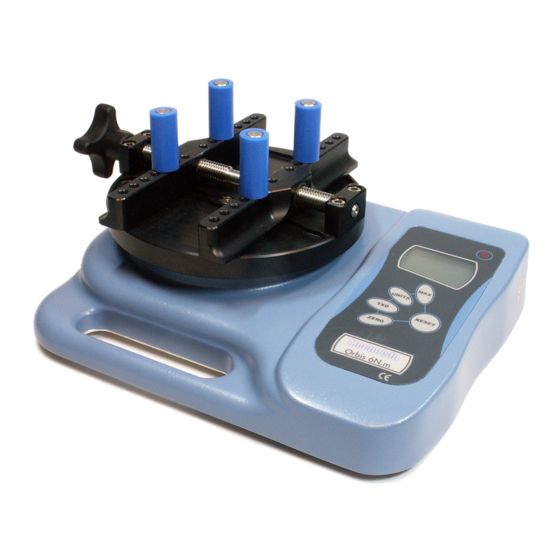
Page 4: The Orbis
Orbis is easy to use by all operators. Before Use Upon receiving the unit please check that no physical damage has occurred to the packaging material, plastic case or the instrument itself. If any damage is evident please notify Mecmesin Corporation immediately. Operation The most commonly used features such as displaying torque, peak hold, zero and changing of displayed units can all be done by pressing a single dedicated key on the front panel. -
Page 5: Assembly Of The Orbis
Align the top plate with the torque drive so that the handle is on the left-hand When Orbis is in transit, the top side of the top plate. Using the 2.5mm Allen key (provided), plate is removed to avoid tighten the two socket countersunk screws hand-tight. -
Page 6: Powering-Up The Orbis
Powering-up the The Orbis is supplied with a set of 5 Nickel Metal Hydride Orbis AAA rechargeable batteries. For safety reasons during transportation the batteries are shipped discharged. To obtain maximum battery life we recommend that you charge them with the charger/adaptor supplied for at least 14 - 16 hours when you first receive the Orbis. -
Page 7: Using The Orbis
Using the Orbis The Orbis is supplied with 4 pegs which grip the sample Fitting accessories during testing. Screw the pegs into the runners on the top fixture equally spaced to ensure the sample is securely gripped when the runners are brought together using the star handle on the end of the lead screws. - Page 8 To power down the Orbis press the red key. Clockwise and Counter- Clockwise torque is displayed on the Orbis and recognized clockwise Values by the symbol shown in Fig. 2. Counter-clockwise torque is displayed on the Orbis and recognized by the symbol shown in Fig. 3c.
- Page 9 – see fig. 3b & 3c Zeroing the Orbis During the operation of the Orbis it is sometimes necessary to zero the display – e.g. when you wish to tare out a displayed torque applied by the sample, so it does not become part of the measured reading.
- Page 10 Fig. 3a Dual Max Max counter- clockwise Direction of reading torque currently applied Max clockwise reading Torque currently applied Max Clockwise Torque Press the MAX key again and the display will show the maximum clockwise torque identified by its symbol. Fig.
- Page 11 TX will disappear from the display. peripheral devices – contact your supplier. Please note that the continuous data stream only starts when approximately 2% of the rated capacity of the Orbis is reached. To differentiate between clockwise and counter-clockwise Removal of minus sign for...
-
Page 12: Optional Settings
Optional Settings Backlit It is possible to activate a back-light on the Orbis display. Display Press and hold RESET whilst powering-up the Orbis with the key. The back-light is now operating. Please note that battery consumption is doubled when using the back-light. - Page 13 If the difference in offset is between 5 - 10 please contact your supplier to arrange a re-calibration of your Orbis. If the difference in offset is greater than 10 please contact your supplier to arrange for a transducer replacement. These values are given as an indicator only –...
-
Page 14: Dimensions
Dimensions Pin Out: Analog Output RS232 Transmit RS232 Receive Mitutoyo Clock Output Mitutoyo Ready Output not used not used not used not available Ground Mitutoyo Request Input Mitutoyo Data Output not used not used not used Allocation for the pins on the female 15 way ‘D Type’... -
Page 15: Orbis Specification Table
0 - 10N.m, 0 - 100kgf.cm, 0 - 90lbf.in Units:- N.m, N.cm, mN.m, gf.cm, kgf.cm, kgf.m, lbf.ft, lbf.in, ozf.in N N o o t t e e : : the units given above will differ depending on the capacity of Orbis chosen Accuracy ± 0.5% of full scale Output •... -
Page 16: The Orbis Te
(2 peak) are calculated. When setting up the Orbis TE a graphical representation of the test provides a clear insight into the % drop factor required. Please contact Mecmesin Corporation or your approved supplier for details on DataPlot graphical charting software. -
Page 17: Optional Settings
Optional Settings Turning on and using the The option menu is accessed via pressing both the RESET & TE option ZERO keys when turning the instrument on. The % drop feature is turned On and Off by pressing the RESET Key. Setting the % drop Ensure that the % drop feature is On. - Page 18 MultiTest The MultiTest 1 is a budget-priced, potentiometer- controlled test stand with 1000 newton capacity. When used with a Mecmesin Corporation force gage and appropriate fixtures this system is ideal for relatively straightforward testing applications; the force gage captures maximum tensile and compressive loads.
- Page 19 Mecmesin Corporation’s powerful, flexible and user-friendly Emperor software. To view our range of accessories please request our brochure by calling 703 433 9247 or visit our website and download the brochure under ‘Literature &...
- Page 20 45921 Maries Road Suite 120 Sterling Virginia 20166 U.S.A. 703-433-9247 703-444-9860 www.mecmesin.com usa-sales@mecmesin.com DISTRIBUTOR STAMP...
Need help?
Do you have a question about the Orbis and is the answer not in the manual?
Questions and answers