Table of Contents
Advertisement
Quick Links
Installation, Operation & Maintenance Manual
Email:
Office 800-648-5438
IMPORTANT:
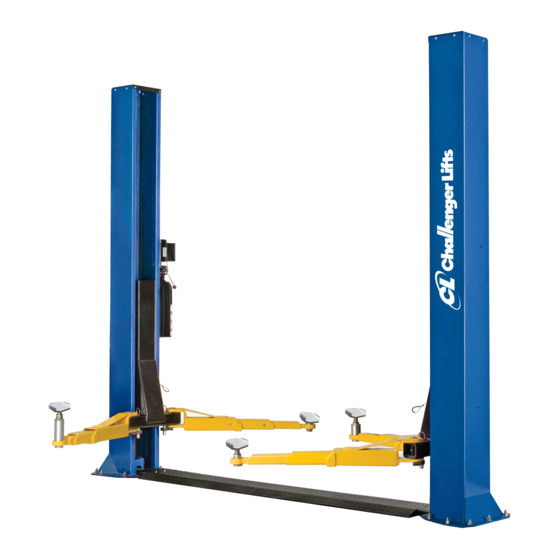
Two Post
Surface Mounted Lift
M
ODEL
9,000
LBS
2,250
LBS
2311 South Park Rd Louisville, Kentucky 40219
sales@challengerlifts.com
/
502-625-0700 Fax 502-587-1933
READ THIS MANUAL COMPLETELY BEFORE
INSTALLING or OPERATING LIFT
CLFP9
. C
APACITY
.
A
PER
RM
Web site:
www.challengerlifts.com
Rev. 2023/11/15
Advertisement
Table of Contents

Subscribe to Our Youtube Channel
Related Manuals for Challenger Lifts CLFP9


Summary of Contents for Challenger Lifts CLFP9
- Page 1 Installation, Operation & Maintenance Manual Two Post Surface Mounted Lift CLFP9 ODEL 9,000 APACITY 2,250 2311 South Park Rd Louisville, Kentucky 40219 Email: Web site: sales@challengerlifts.com www.challengerlifts.com Office 800-648-5438 502-625-0700 Fax 502-587-1933 IMPORTANT: READ THIS MANUAL COMPLETELY BEFORE INSTALLING or OPERATING LIFT...
-
Page 2: General Specifications
Model CLFP9 Installation, Operation and Maintenance ENERAL PECIFICATIONS See Figure 1 CLFP9 120 7/8” Column Height 78 1/8” Rise Height (Screw Pads Highest Position) 4” to 5 7/8” Screw Pad Height 137 1/2" Overall Width 109” Inside of Columns Drive Thru Clearance 98 3/16”... - Page 3 Model CLFP9 Installation, Operation and Maintenance Safety decals similar to those shown here are ERTICAL LEARANCE found on a properly installed lift. Be sure that all Check the height of the area where the lift is to be safety decals have been correctly installed on the installed.
- Page 4 Model CLFP9 Installation, Operation and Maintenance ECEIVING NSTALLATION The shipment should be thoroughly inspected as AFETY EQUIREMENTS FOR NSTALLATION AND soon as it is received. The signed bill of lading is ERVICE acknowledgement by the carrier of receipt in Refer to ANSI/ALI ALIS (current edition)
- Page 5 Model CLFP9 Installation, Operation and Maintenance 7) Assemble a washer and nut to the anchor 12) Thread 9/16-18 O-ring elbow ( in hardware box with nut just below impact section of bolt. into power unit. Attach free end of power unit Drive the anchor into the hole until the nut is hose to elbow.
- Page 6 Model CLFP9 Installation, Operation and Maintenance Fig 6-Lower Sheaves 18) Route the cable under the bottom sheave, along the drive over channel and under the bottom sheave of the opposite column and reassemble. 19) Remove the cable trapping bolt assembly, Fig 7, on the top sheave.
- Page 7 Model CLFP9 Installation, Operation and Maintenance LECTRICAL INAL DJUSTMENTS 26) Have a certified electrician connect the YDRAULICS power unit to a suitable electrical power 32) Pressure test hydraulic system. Energize source. The standard power unit is 208/230 power unit, raise lift to full rise and continue volt 60 Hz single phase requiring a dedicated to run motor for additional 10 seconds.
- Page 8 Model CLFP9 Installation, Operation and Maintenance Fig 10 – Electrical Wiring Diagram Page 8 CLFP9-IOM-A.doc Rev. 2023/11/15...
-
Page 9: Operation Procedure
Model CLFP9 Installation, Operation and Maintenance The Owner/Employer shall display the lift PERATION ROCEDURE manufacturer’s operating instructions; ALI/SM, ALI Lifting it Right safety manual; ALI/ST, AFETY OTICES AND ECALS ALI Safety Tips card; ANSI/ALI ALOIM, American This product is furnished with graphic safety... - Page 10 Model CLFP9 Installation, Operation and Maintenance IFTING A EHICLE AINTENANCE 1) Ensure that the lifting arms are parked, out to To avoid personal injury, permit only qualified full drive thru position. personnel to perform maintenance on this equipment. Maintenance personnel should follow 2) Center the vehicle between the columns in the lockout/tagout instructions per ANSI Z244.1.
-
Page 11: Parts Breakdown
M10x25mm HEX FLANGE HEAD BOLT Replace all worn or broken parts with genuine Challenger Lifts Inc. parts. Contact your local Challenger Lifts Parts Distributor for pricing and availability. (Call Challenger Lifts Inc. (502) 625-0700 for the Parts Distributor in your area) Page 11 CLFP9-IOM-A.doc... -
Page 12: Fig B. Lock
COTTER PIN, Ø2.5mm X 20mm Replace all worn or broken parts with genuine Challenger Lifts Inc. parts. Contact your local Challenger Lifts Parts Distributor for pricing and availability. (Call Challenger Lifts Inc. (502) 625-0700 for the Parts Distributor in your area) Page 12 CLFP9-IOM-A.doc... -
Page 13: Fig C. Hydraulics
B31095 Replace all worn or broken parts with genuine Challenger Lifts Inc. parts. Contact your local Challenger Lifts Parts Distributor for pricing and availability. (Call Challenger Lifts Inc. (502) 625-0700 for the Parts Distributor in your area) Page 13 CLFP9-IOM-A.doc... -
Page 14: Fig D. Synchronizer
73P DRIVE CHAIN Replace all worn or broken parts with genuine Challenger Lifts Inc. parts. Contact your local Challenger Lifts Parts Distributor for pricing and availability. (Call Challenger Lifts Inc. (502) 625-0700 for the Parts Distributor in your area) Page 14 CLFP9-IOM-A.doc... - Page 15 ARM ASSEMBLY ITEMS: 58, 59, 60, 61, 63, 70, 78, 79, 80, 81, 82, 83 Replace all worn or broken parts with genuine Challenger Lifts Inc. parts. Contact your local Challenger Lifts Parts Distributor for pricing and availability. (Call Challenger Lifts Inc. (502) 625-0700 for the Parts Distributor in your area) Page 15 CLFP9-IOM-A.doc...
- Page 16 DRIVE OVER CHANNEL Replace all worn or broken parts with genuine Challenger Lifts Inc. parts. Contact your local Challenger Lifts Parts Distributor for pricing and availability. (Call Challenger Lifts Inc. (502) 625-0700 for the Parts Distributor in your area) Page 16 CLFP9-IOM-A.doc...
- Page 17 Model CLFP9 Installation, Operation and Maintenance REVISIONS 2021/08/17 – UPDATED THE ANSI/ALI ALCTV AND ALOIM. OUTDOOR USED IS PROHIBITED. 2023/11/15 – UPDATED ANSI/ALI REFERENCE MATERIAL. UPDATED ANCHORING INSTRUCTIONS. Pg. 4 Page 17 CLFP9-IOM-A.doc Rev. 2023/11/15...
Need help?
Do you have a question about the CLFP9 and is the answer not in the manual?
Questions and answers