Advertisement
Quick Links
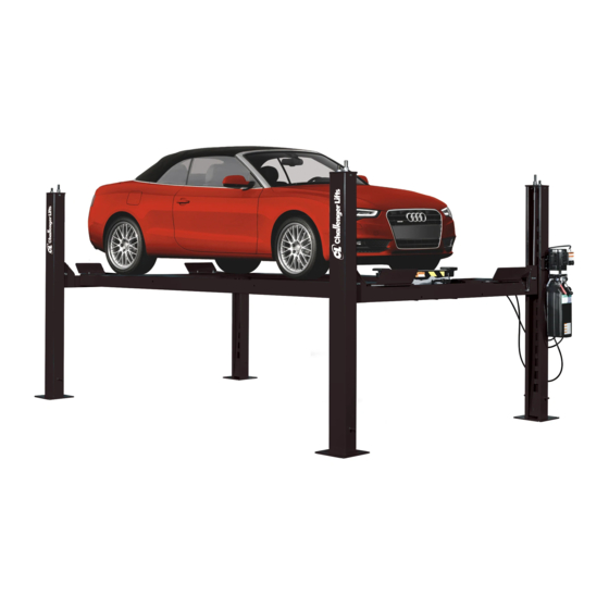
Installation, Operation & Maintenance Manual
Four Post
Surface Mounted Lift
Models CL4P7
(7,000 lb Capacity)
2311 South Park Rd Louisville, Kentucky 40219
Email:sales@challengerlifts.com
Web
site:www.challengerlifts.com
/
Office 800-648-5438
502-625-0700 Fax 502-587-1933
IMPORTANT:
READ THIS MANUAL COMPLETELY BEFORE
INSTALLING or OPERATING LIFT
Rev. 03/11/2019
Advertisement

Subscribe to Our Youtube Channel
Related Manuals for Challenger Lifts CL4P7


Summary of Contents for Challenger Lifts CL4P7
- Page 1 Installation, Operation & Maintenance Manual Four Post Surface Mounted Lift Models CL4P7 (7,000 lb Capacity) 2311 South Park Rd Louisville, Kentucky 40219 Email:sales@challengerlifts.com site:www.challengerlifts.com Office 800-648-5438 502-625-0700 Fax 502-587-1933 IMPORTANT: READ THIS MANUAL COMPLETELY BEFORE INSTALLING or OPERATING LIFT Rev. 03/11/2019...
-
Page 2: General Specifications
Model CL4P7 Installation, Operation and Maintenance ENERAL PECIFICATIONS CL4P7 SPECIFICATIONS 195½” [16’-3 1/2”] Length Overall 100 1/2” (8’-4 1/2”) Width Overall 92 1/8” Inside Columns 147 ½” [12’-3 1/2”] Between Columns 79 1/2” Height of Columns 5 ¾” min – 70 1/2” max Height of Runway, Floor to runway top 20”... - Page 3 Model CL4P7 Installation, Operation and Maintenance Fig 2 – Drive Under Height (On Locks) Rev. 03/11/2019 Q4P07-IOM-A.doc...
-
Page 4: Vertical Clearance
Model CL4P7 Installation, Operation and Maintenance ERTICAL LEARANCE AFETY OTICES AND ECALS Check the height of the area where the lift is to be For your safety, and the safety of others, read and installed. Clearance should be calculated based on understand all of the safety notices and decals the full raised height of the lift. -
Page 5: Installation
Do this for your own ENTRANCE RAMP protection. CROSS BEAM ASS’Y NOTIFY Challenger Lifts AT ONCE if any hidden loss or damage is discovered after receipt. POWER UNIT IT IS DIFFICULT TO COLLECT FOR LOSS OR... - Page 6 Model CL4P7 Installation, Operation and Maintenance Fig 4 – Lock Clevis OLUMNS 5) Remove the top cap and ladder bar from each column assembly and place the columns close to each corner per layout (Column with the power Fig 5 – Column/Cross Beam Assembly unit bracket goes at the front left column position per Fig 1).
- Page 7 Model CL4P7 Installation, Operation and Maintenance 10) Remove the four (4) cross beam sheaves (one sheave from each beam end). DO NOT REMOVE THE RUNWAY SHEAVE PINS. 11) Place the mechanical lock release rod into the saddles located on the inside of the cross beams, Fig 8.
- Page 8 Model CL4P7 Installation, Operation and Maintenance 19) Center cross beam bolts with slots in runway 23) Repeat for the remaining three columns. and tighten. (Be careful not to move runways.) PTIONAL NCHORING 20) Reassembly the lock ladder and top cap to NOTE: Lift must be anchored in place if slope column.
- Page 9 Model CL4P7 Installation, Operation and Maintenance 32) For installs on the front of the column (Fig 16), rout the power unit supply line to the bulkhead shown below. Attach the 90 degree fitting at a slight angle downward and secure the hose to the fitting.
- Page 10 Model CL4P7 Installation, Operation and Maintenance 37) Connect the power unit to a suitable electrical power source. The standard power unit is 115 volt 50/60 Hz single phase requiring a dedicated single throw circuit breaker to operate lift at full capacity. For 230V power unit, refer to Fig 22.
-
Page 11: Operation Procedure
Model CL4P7 Installation, Operation and Maintenance FOR SINGLE PHASE (Normally Open) FIELD CONECTIONS Fig 22 – NON STANDARD 230V WIRING DIAGRAM Lifts-Safety Requirements for Operation, Inspection PERATION ROCEDURE and Maintenance; and the employer shall insure AFETY OTICES AND ECALS that the lift maintenance personnel are qualified and... - Page 12 Model CL4P7 Installation, Operation and Maintenance IFTING A EHICLE AINTENANCE Place entrance ramps in the slotted holes on the To avoid personal injury, permit only qualified front of the ramp. Drive vehicle onto lift. Set personnel to perform maintenance on this parking brake.
- Page 13 Model CL4P7 Installation, Operation and Maintenance PTIONAL CCESSORIES (Q4P09CS) OBILITY (Q4P09DT) 1) This set of four casters when attached to the 1) Place drip tray between runways in the Jack rail, cross beams of an unloaded lift, Fig 27, pick Fig 24.
- Page 14 Parts Breakdown Models CL4P7 IMPORTANT!!! Replace all worn, damaged, or broken parts with parts approved by Challenger Lifts Inc. or with parts meeting Challenger Lifts Inc. specifications. Contact your local Challenger Lifts Parts Distributor for pricing and availability. (Call Challenger Lifts Inc. (502) 625-0700 for the Parts Distributor in your area) Rev.
- Page 15 Model CL4P7 Installation, Operation and Maintenance Parts Breakdown Fig A. General Layout Rev. 03/11/2019 Q4P07-IOM-A.doc...
- Page 16 3/8-18 NPT x M14x1.5 90 DEGREE HYD. FITTING TCS4-12-00 REMOVABLE WHEEL STOP Replace all worn, damaged, or broken parts with parts approved by Challenger Lifts Inc. or with parts meeting Challenger Lifts Inc. specifications. Contact your local Challenger Lifts Parts Distributor for pricing and availability.
- Page 17 X10-040 M12 NUT M18 NUT Replace all worn, damaged, or broken parts with parts approved by Challenger Lifts Inc. or with parts meeting Challenger Lifts Inc. specifications. Contact your local Challenger Lifts Parts Distributor for pricing and availability. (Call Challenger Lifts Inc. (502) 625-0700 for the Parts Distributor in your area) Rev.
- Page 18 RUNWAY SHEAVE SPACER – TALL TCS3-5-07-02 RUNWAY SHEAVE SPACER - SHORT Replace all worn, damaged, or broken parts with parts approved by Challenger Lifts Inc. or with parts meeting Challenger Lifts Inc. specifications. Contact your local Challenger Lifts Parts Distributor for pricing and availability.
- Page 19 Model CL4P7 Installation, Operation and Maintenance PARTS BREAKDOWN (continued) Fig D. Cross Beams Rev. 03/11/2019 Q4P07-IOM-A.doc...
- Page 20 Model CL4P7 Installation, Operation and Maintenance Rev. 03/11/2019 Q4P07-IOM-A.doc...
- Page 21 TCS3-5-21 ROLL PIN, Ø6mm X 24mm Lg. Replace all worn, damaged, or broken parts with parts approved by Challenger Lifts Inc. or with parts meeting Challenger Lifts Inc. specifications. Contact your local Challenger Lifts Parts Distributor for pricing and availability.
Need help?
Do you have a question about the CL4P7 and is the answer not in the manual?
Questions and answers