Table of Contents
Advertisement
Quick Links
Installation, Operation & Maintenance Manual
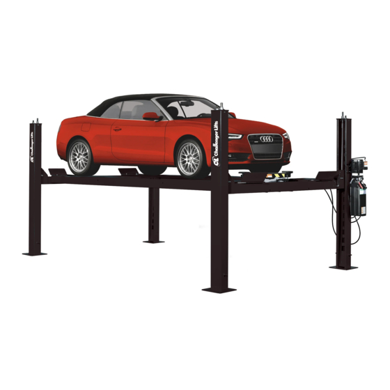
Four Post
Surface Mounted Lift
Models CL4P9S, CL4P9X & CL4P9W
(9,000 lb Capacity)
2311 South Park Rd Louisville, Kentucky 40219
Email:sales@challengerlifts.com
Web
site:www.challengerlifts.com
/
Office 800-648-5438
502-625-0700 Fax 502-587-1933
IMPORTANT:
READ THIS MANUAL COMPLETELY BEFORE
INSTALLING or OPERATING LIFT
Rev 12/15/2020
Advertisement
Table of Contents


Need help?
Do you have a question about the CL4P7 and is the answer not in the manual?
Questions and answers