Table of Contents
Advertisement
Quick Links
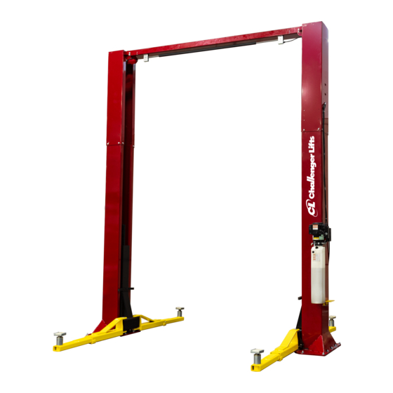
Installation, Operation & Maintenance Manual
Two Post Surface Mounted Lift
M
CL20
ODELS
20,000
C
- 5000
P
A
LBS
APACITY
LBS
ER
RM
2311 South Park Rd Louisville, Kentucky 40219
Email:
Web site:
sales@challengerlifts.com
www.challengerlifts.com
/
Office 800-648-5438
502-625-0700 Fax 502-587-1933
IMPORTANT:
READ THIS MANUAL COMPLETELY BEFORE
INSTALLING or OPERATING LIFT
Rev. 08/23/2021
Advertisement
Table of Contents

Related Manuals for Challenger Lifts CL20


Summary of Contents for Challenger Lifts CL20
- Page 1 Installation, Operation & Maintenance Manual Two Post Surface Mounted Lift CL20 ODELS 20,000 - 5000 APACITY 2311 South Park Rd Louisville, Kentucky 40219 Email: Web site: sales@challengerlifts.com www.challengerlifts.com Office 800-648-5438 502-625-0700 Fax 502-587-1933 IMPORTANT: READ THIS MANUAL COMPLETELY BEFORE INSTALLING or OPERATING LIFT...
-
Page 2: General Specifications
Model CL20 Installation, Operation and Maintenance ENERAL PECIFICATIONS CL20-0 CL20-2 See Figure 1 -6” -12” -6” -12” 174” 168” 162” 198” 192” 186” Column Height [14’-6”] [14’-0”] [13’-6”] [16’-6”] [16’-0] [15’-6] Ceiling Height Required 176” 170” 164” 200” 194” 188”... - Page 3 Model CL20 Installation, Operation and Maintenance EAD ENTIRE MANUAL BEFORE ASSEMBLING ERTICAL LEARANCE INSTALLING OPERATING OR SERVICING THIS Check the height of the area where the lift is to be EQUIPMENT installed. Clearance should be calculated based on ROPER MAINTENANCE AND INSPECTION IS NECESSARY the full raised height of the lift.
-
Page 4: Installation
Model CL20 Installation, Operation and Maintenance ECEIVING NSTALLATION The shipment should be thoroughly inspected as AFETY EQUIREMENTS FOR NSTALLATION AND soon as it is received. The signed bill of lading is ERVICE acknowledgement by the carrier of receipt in good Refer to ANSI/ALI ALIS (current edition) condition of shipment covered by our invoice. - Page 5 Model CL20 Installation, Operation and Maintenance 5) Determine the sheave location on the bracket 7) Route a cable through a carriage and out the based on Column Extension Height, see Fig 2. bottom. Route it back up and into the inside hole Note: The column has been assembled with at the top of the carriage, see Fig 2.
- Page 6 Model CL20 Installation, Operation and Maintenance 18) Raise both carriages (400 lbs. ea.) high enough ELEASE to drill the two inner anchor holes on each column. Measure both carriage heights to ensure they are in the same lock position. 19) IMPORTANT: Place a safety support inside each...
- Page 7 Model CL20 Installation, Operation and Maintenance COLUMN COLUMN COLUMN COLUMN EXTENSION EXTENSION EXTENSION EXTENSION TABS TABS TABS TABS INSTALLATION AID INSTALLATION AID INSTALLATION AID INSTALLATION AID INSTALL 1/2" HEX FLANGE BOLT INSTALL 1/2" HEX FLANGE BOLT INSTALL 1/2" HEX FLANGE BOLT INSTALL 1/2"...
- Page 8 Model CL20 Installation, Operation and Maintenance 30) Mount synchronizer cables to carriages as shown in Fig. 10. Note: Use the proper Take- Up Tube as shown in Fig 10 based on the width of the lift. YDRAULICS IMPORTANT: To ensure proper hose fitting seal...
- Page 9 Model CL20 Installation, Operation and Maintenance x 3/4” lg. hex flange bolt and one hex flange nut). Route hose across overhead to the other side. Clamps are not needed yet 37) Uncoil Power Side hose and loosely attach it to...
- Page 10 Model CL20 Installation, Operation and Maintenance 40) If installing a CL16-0, use the Routing Diagram C 41) Route the overhead hose based on the lifts in Fig 14. If installing a CL16-2 use the table in height and width. To make a loop, twist the hose.
- Page 11 Model CL20 Installation, Operation and Maintenance and attach it to the idler side lock release air ELEASE cylinder (Fig. 17). 48) Assemble the fittings to the air valve, Fig. 16, with the barbed fitting (3/8” hose barb x 1/8NPT) in port marked “1”, the elbow (1/8” push-lock x...
-
Page 12: Arm Installation
Model CL20 Installation, Operation and Maintenance 58) Install the Lock Release Covers on the Power and Idler Columns. NSTALLATION 59) Lubricate the arm pin or carriage arm pin hole with “anti-seize” and install the arms. Install the Arm Pin Snap Ring. -
Page 13: Final Adjustments
Model CL20 Installation, Operation and Maintenance YNCHRONIZING ABLES INAL DJUSTMENTS 78) Raise lift and ensure carriages lower into same YDRAULICS lock position. 73) Lower the lift to the floor and raise the lift 79) Adjust synchronizing cables so the tension is approximately one foot. - Page 14 Model CL20 Installation, Operation and Maintenance Wiring Diagram FOR SINGLE PHASE (Normally Open) FIELD CONNECTIONS LOAD INPUT FOR THREE PHASE FACTORY WIRED FOR 208−240V RECONNECTIONS FOR 440−480V Fig 21 – Electrical Wiring Diagram Page 14 Rev. 08/23/2021 CL20-IOM-A.doc...
-
Page 15: Operation Procedure
Model CL20 Installation, Operation and Maintenance The Owner/Employer shall display the lift PERATION ROCEDURE manufacturer’s operating instructions; ALI/SM 93 -1, ALI Lifting it Right safety manual; ALI/ST- AFETY OTICES AND ECALS 90 ALI Safety Tips card; ANSI/ALI ALOIM, This product is furnished with graphic safety... - Page 16 Model CL20 Installation, Operation and Maintenance IFTING A EHICLE OSS OF POWER 1) Ensure that the lifting arms are parked, out to full If for any reason the lift will not raise off the locks or drive thru position. the locks will not retract, consult factory authorized personnel.
-
Page 17: Maintenance
Check for loose or broken parts. Check hydraulic system for fluid leaks. Check adapters for damage or excessive wear. Replace as required with genuine Challenger Lifts parts. Check lock release activation. Each Column Lock should move freely. When the Air Cylinder is fully extended, the Column Lock should rest firmly against the back of the column. - Page 18 Model CL20 Installation, Operation and Maintenance Page 18 Rev. 08/23/2021 CL20-IOM-A.doc...
-
Page 19: Parts Breakdown
12310-2 COLUMN EXTENSION PACK (16’-6” O.A. Ht.) Items (2, 13, 14, 66, 67, 68, 69) Replace all worn, damaged, or broken parts with parts approved by Challenger Lifts Inc. or with parts meeting Challenger Lifts Inc. specifications. Contact your local Challenger Lifts Parts Distributor for pricing and availability. - Page 20 Model CL20 Installation, Operation and Maintenance PARTS BREAKDOWN (continued) Fig B. Lock-Power/Idler Page 20 Rev. 08/23/2021 CL20-IOM-A.doc...
- Page 21 ANCHOR BOLT, 3/4” x 5 1/2” lg 37072 SNAP ON LOCK COVER Replace all worn, damaged, or broken parts with parts approved by Challenger Lifts Inc. or with parts meeting Challenger Lifts Inc. specifications. Contact your local Challenger Lifts Parts Distributor for pricing and availability.
- Page 22 1/4 WASHER 12748 NYLON SPACER 1/4x1/4 Replace all worn, damaged, or broken parts with parts approved by Challenger Lifts Inc. or with parts meeting Challenger Lifts Inc. specifications. Contact your local Challenger Lifts Parts Distributor for pricing and availability. (Call Challenger Lifts Inc. (502) 625-0700 for the Parts Distributor in your area) Page 22 Rev.
- Page 23 0 / 2 / 4 6” TAKE-UP TUBES [ STD HEIGHT: 0 -6: 2 -12: 4 ] Replace all worn, damaged, or broken parts with parts approved by Challenger Lifts Inc. or with parts meeting Challenger Lifts Inc. specifications. Contact your local Challenger Lifts Parts Distributor for pricing and availability.
- Page 24 M8 x 30 SOCKET HEAD CAP SCREW B12048S-1 ARM ASSEMBLY, 3-STAGE Replace all worn, damaged, or broken parts with parts approved by Challenger Lifts Inc. or with parts meeting Challenger Lifts Inc. specifications. Contact your local Challenger Lifts Parts Distributor for pricing and availability.
- Page 25 Model CL20 Installation, Operation and Maintenance REVISIONS 08/23/2021- CREATED FOR NEW PRODUCT RELEASE Page 25 Rev. 08/23/2021 CL20-IOM-A.doc...
Need help?
Do you have a question about the CL20 and is the answer not in the manual?
Questions and answers