Table of Contents
Advertisement
Installation, Operation & Maintenance Manual
V
M
ODELS
Email:
Office 800-648-5438
IMPORTANT:
ersymmetric®
Surface Mounted Lift
CL10V3
:
CL10V3-QC
10,000
2500
2311 South Park Rd Louisville, Kentucky 40219
sales@challengerlifts.com
/
502-625-0700 Fax 502-587-1933
READ THIS MANUAL COMPLETELY BEFORE
INSTALLING or OPERATING LIFT
Two Post
(Q
UICK
. C
LBS
APACITY
.
A
LBS
PER
RM
Web site:
www.challengerlifts.com
C
)
YCLE
Rev. 01/02/2020
Advertisement
Table of Contents

Subscribe to Our Youtube Channel
Related Manuals for Challenger Lifts Versymmetric


Summary of Contents for Challenger Lifts Versymmetric
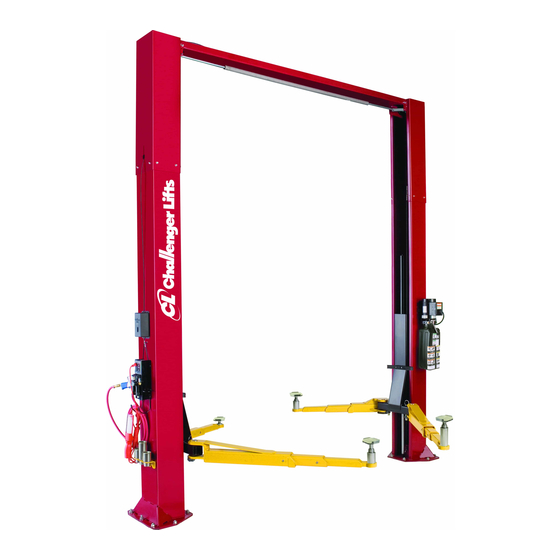
- Page 1 Installation, Operation & Maintenance Manual ersymmetric® Two Post Surface Mounted Lift CL10V3 ODELS CL10V3-QC UICK YCLE 10,000 APACITY 2500 2311 South Park Rd Louisville, Kentucky 40219 Email: Web site: sales@challengerlifts.com www.challengerlifts.com Office 800-648-5438 502-625-0700 Fax 502-587-1933 IMPORTANT: READ THIS MANUAL COMPLETELY BEFORE INSTALLING or OPERATING LIFT Rev.
-
Page 2: Specifications
Model CL10 Installation, Operation and Maintenance ENERAL PECIFICATIONS See Figure 1 CL10 CL10-2 CL10-3 11’-2” or 11’- 8” 13’-2” or 13’- 8” 14’-2” or 14’- 8” Column Height 10’-8 1/2” or 11’- 2 1/2 ” 12’- 8 1/2” or 13’- 2 1/2” 13’- 8 1/2” or 14’- 2 1/2” Floor to Overhead Switch 74 1/8”... -
Page 3: Vertical Clearance
Model CL10 Installation, Operation and Maintenance EAD ENTIRE MANUAL BEFORE ASSEMBLING ERTICAL LEARANCE INSTALLING OPERATING OR SERVICING THIS Check the height of the area where the lift is to be EQUIPMENT installed. Clearance should be calculated based on ROPER MAINTENANCE AND INSPECTION IS the full raised height of the lift. - Page 4 Chalk line shorted or damaged goods. Do this for your own c. 4ft level protection. d. 10” adjustable wrench Challenger Lifts NOTIFY AT ONCE if any e. Standard open end wrenches 7/16”, 1/2", hidden loss or damage is discovered after receipt.
-
Page 5: Important Note
Model CL10 Installation, Operation and Maintenance 4) Re-install cable trapping hardware and slide carriage and cylinder back down to base of lift. Ensure hydraulic hose is routed around base tabs properly to prevent rotation of the cylinder. IMPORTANT NOTE: If the lift is to be installed in the Narrow (11’- 6 ½”) or Reduced Height Setting (11’-2”, 13- 2”, 14’-2”),... - Page 6 Model CL10 Installation, Operation and Maintenance Fig. 5 – Column Shimming 16) Tighten power column anchors and recheck column for plumb. Re-shim if necessary. Fig. 7a – Overhead Limit Switch Power Side Torque to 150 foot pounds to set anchors. 20) Install the Idler Bracket to the Overhead Beam VERHEAD using the rear set of holes on the Idler Side of...
- Page 7 Model CL10 Installation, Operation and Maintenance Fig. 9b – Jam Nut & H OWER YDRAULIC OSES POWER UNIT HOSE Fig. 8 – Column Ext. Cable Trapping 'O' RING ELBOW 24) Mount synchronizer cables to carriages as shown in Fig. 9a & 9b . Note: The 4 ½” & 12” take up tubes are to take up the sync.
- Page 8 Model CL10 Installation, Operation and Maintenance " HOSE CLAMPS -20NC NUT NYLON SPACER IDLER HOSE HYD. LINE CLAMP -20NC x BOLT HOSE CLAMP "-16 x " BOLT " NUT -16NC x BOLT -16NC NUT Fig. 12 – Power Unit Hose 28) Thread 9/16-18 O-ring elbow ( in hardware box into power unit.
- Page 9 Model CL10 Installation, Operation and Maintenance 32) Route opposite end of cable assembly up Power the small outer gear to align itself with the inner Column and into column through access slot in large gear and tighten the bolts. bottom of Column Extension. Following the path 39) Make sure all the arm bolts are tight.
- Page 10 Model CL10 Installation, Operation and Maintenance 54) Cycle lift to insure that latches operate simultaneously. ELEASE ABLE 55) Lower lift to the floor and snap plastic cover over Power Column lock assembly. 56) Pull and release Power Column lock release handle while watching Idler Column lock.
-
Page 11: Wiring Diagram
Model CL10 Installation, Operation and Maintenance Wiring Diagram FOR SINGLE PHASE FIELD CONECTIONS (Normally Open) FIELD CONECTIONS FOR THREE PHASE FACTORY WIRED FOR 208−240V RECONNECTIONS FOR 440−480V Fig. 16 – Electrical Wiring Diagram Page 11 Rev 01/02/2020 CL10-IOM-A.doc... -
Page 12: Operation Procedure
Model CL10 Installation, Operation and Maintenance National Standard for Automotive Lifts-Safety PERATION ROCEDURE Requirements Operation, Inspection Maintenance; and in the case of frame engaging AFETY OTICES AND ECALS lift, ALI/LP-GUIDE, Vehicle Lifting Points/Quick This product is furnished with graphic safety Reference Guide for Frame Engaging Lifts;... -
Page 13: Installation
If the Check adapters for damage or excessive wear. vehicle seems unstable, lower the lift and Replace as required with genuine Challenger Lifts readjust the arms. If the vehicle is stable, raise parts. -
Page 14: Parts Breakdown
31058 ANCHOR BOLT, 3/4 x 5-1/2” Lg. Replace all worn, damaged, or broken parts with parts approved by Challenger Lifts Inc. or with parts meeting Challenger Lifts Inc. specifications. Contact your local Challenger Lifts Parts Distributor for pricing and availability. -
Page 15: Fig B. Lock
36096 BALL HANDLE – Power side ONLY Replace all worn, damaged, or broken parts with parts approved by Challenger Lifts Inc. or with parts meeting Challenger Lifts Inc. specifications. Contact your local Challenger Lifts Parts Distributor for pricing and availability. -
Page 16: Fig C. Hydraulics
¼-20 x ¾ HEX FLANGE HEAD BOLT 40085 ¼-20 HEX FLANGE NUT Replace all worn, damaged, or broken parts with parts approved by Challenger Lifts Inc. or with parts meeting Challenger Lifts Inc. specifications. Contact your local Challenger Lifts Parts Distributor for pricing and availability. -
Page 17: Fig D. Synchronizer
A2158 1/4 DIA. x 1 3/4" Lg CLEVIS PIN Replace all worn, damaged, or broken parts with parts approved by Challenger Lifts Inc. or with parts meeting Challenger Lifts Inc. specifications. Contact your local Challenger Lifts Parts Distributor for pricing and availability. - Page 18 PARTS BREAKDOWN (continued) Fig E. Carriage & 3-Stage Arm Pack (B2202SD) Replace all worn, damaged, or broken parts with parts approved by Challenger Lifts Inc. or with parts meeting Challenger Lifts Inc. specifications. Contact your local Challenger Lifts Parts Distributor for pricing and availability.
- Page 19 B2204SD REAR ARM ASSY. Items: 73-93,100,101 Replace all worn, damaged, or broken parts with parts approved by Challenger Lifts Inc. or with parts meeting Challenger Lifts Inc. specifications. Contact your local Challenger Lifts Parts Distributor for pricing and availability. (Call Challenger Lifts Inc. (502) 625-0700 for the Parts Distributor in your area)
- Page 20 B2302SD ARM PACK, CL10, 2/3-STAGE (items 105-117) Replace all worn, damaged, or broken parts with parts approved by Challenger Lifts Inc. or with parts meeting Challenger Lifts Inc. specifications. Contact your local Challenger Lifts Parts Distributor for pricing and availability.
- Page 21 Model CL10 Installation, Operation and Maintenance NOTES Page 21 Rev 01/02/2020 CL10-IOM-A.doc...
- Page 22 Model CL10 Installation, Operation and Maintenance NOTES Page 22 Rev 01/02/2020 CL10-IOM-A.doc...
- Page 23 Model CL10 Installation, Operation and Maintenance REVISIONS 11/21/2019- ADDED ANCHOR BOLTS TO THE PBD. CORRECT THE SYNC CABLE PART NUMBERS AND THE COLUMN WELD PART NUMBERS IN THE PBD. UPDATED SAFETY REQUIREMENTS FOR INSTALLATION AND SERVICE. ADDED STEP TO CHECK THE ARM STOP BOLTS TO MAKE SURE THEY ARE TIGHT.
Need help?
Do you have a question about the Versymmetric and is the answer not in the manual?
Questions and answers