Advertisement
Installation, Operation & Maintenance Manual
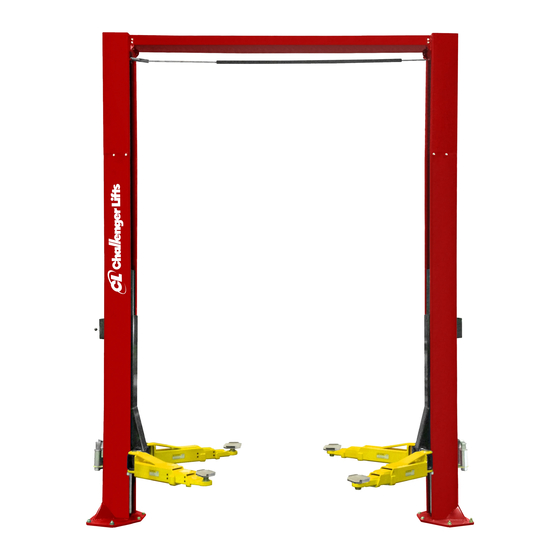
Two Post Surface Mounted Lift
Email:
Office 800-648-5438
IMPORTANT:
M
ODEL
12,000
LBS
3000
LBS
2311 South Park Rd, Louisville, Kentucky 40219
sales@challengerlifts.com
/
502-625-0700 Fax 502-587-1933
READ THIS MANUAL COMPLETELY BEFORE
INSTALLING or OPERATING LIFT
CL12
. C
APACITY
.
A
PER
RM
Web site:
www.challengerlifts.com
Rev. 10/23/19
Advertisement
Table of Contents

Related Manuals for Challenger Lifts CL12 Series


Summary of Contents for Challenger Lifts CL12 Series
- Page 1 Installation, Operation & Maintenance Manual Two Post Surface Mounted Lift CL12 ODEL 12,000 APACITY 3000 2311 South Park Rd, Louisville, Kentucky 40219 Email: Web site: sales@challengerlifts.com www.challengerlifts.com Office 800-648-5438 502-625-0700 Fax 502-587-1933 IMPORTANT: READ THIS MANUAL COMPLETELY BEFORE INSTALLING or OPERATING LIFT Rev.
-
Page 2: General Specifications
Model CL12 Installation, Operation and Maintenance ENERAL PECIFICATIONS See Figure 1 CL12-LC CL12-0 CL12-1 CL12-2 11’-11” 13’-2” or 13’- 8” 14’-2” or 14’- 8” 15’-2” or 15’- 8” Column Height 11’-4 ½” 12’-8”or 13’- 2” 13’-8” or 14’- 2” 14’-8” or 15’- 2” Floor to Overhead Switch 74 ¾”... - Page 3 Model CL12 Installation, Operation and Maintenance Safety decals similar to those shown here are found ERTICAL LEARANCE on a properly installed lift. Be sure that all safety Check the height of the area where the lift is to be decals have been correctly installed. Verify that all installed.
-
Page 4: Installation
Standard open end wrenches 7/16”, 1/2", shorted or damaged goods. Do this for your own (2) 9/16”, (2) 11/16”, 3/4" protection. 5/16” allen wrench Challenger Lifts NOTIFY AT ONCE if any hidden g. Needle nose pliers loss or damage is discovered after receipt. - Page 5 Model CL12 Installation, Operation and Maintenance 5) Layout the service bay according to the architect’s plans or owner’s instructions (see Fig. 1b). Failure to install in this orientation can result in personal and property damage. Be certain that the proper conditions exist, see pg 3. 6) Assemble column extension to column by lining up the correct set of holes and use the 3/8”-16 x 3/4"...
- Page 6 Model CL12 Installation, Operation and Maintenance Bracket. The narrow slot needs to be facing VERHEAD towards the Power Column. Slide the Shutoff 16) Before raising overhead into position install 4 Bar over the limit switch on the Power Side. Pin each (2 per column) hex flange bolts and nuts in the Shutoff Bar to the Idler Side Bracket with the bottom hole of column extension...
- Page 7 Model CL12 Installation, Operation and Maintenance 22) Mount synchronizer cables to carriages as shown in Fig. 10 . Note: Do Not Use the 12” 23) Install the Hose Guide Brackets and Hose take-up pipe on the 13’-8”, 14’-8”, & 15’-8” Support Tabs to both the Idler &...
- Page 8 Model CL12 Installation, Operation and Maintenance IMPORTANT – To insure proper hose fitting seal 26) Mount Power Unit to power unit bracket on the without damage to the fitting follow this column as shown in Fig. 13 . The mounting procedure for each hose connection: Screw flared hardware, (4) 5/16”-18 hex nuts, are pre-installed fitting on finger tight.
-
Page 9: Arm Installation
Model CL12 Installation, Operation and Maintenance ELEASE NSTALLATION 31) On the power column, attach lock cable 38) Extend the foot pad to both extents and apply assembly to mounting tab using (2) hex jam “anti-seize” to the retaining ring. nuts. Bottom of stud end should stick out 39) Arm restraint assemblies should be installed on approx. - Page 10 Model CL12 Installation, Operation and Maintenance AFETY ECAL LACEMENT 45) Clean surface of the rear column above the power unit and install Safety Decals, Page 3 and Fig. 21 . Fig. 19-Bolt Adjustment DAPTER NSTALLATION 44) Locate the two pre-drilled holes on the back of each column 19”...
- Page 11 Model CL12 Installation, Operation and Maintenance INAL DJUSTMENTS YDRAULICS 49) Lower the lift to the floor and raise the lift approximately one foot. 50) Start with Idler side first. Slowly and carefully loosen the bleed plug on top of the cylinder just enough to allow the entrapped air to escape.
-
Page 12: Wiring Diagram
Model CL12 Installation, Operation and Maintenance Wiring Diagram FOR SINGLE PHASE FIELD CONECTIONS (Normally Open) FIELD CONECTIONS FOR THREE PHASE FACTORY WIRED FOR 208−240V RECONNECTIONS FOR 440−480V Fig. 23 – Electrical Wiring Diagram Page 12 Rev. 10/23/19 CL12-IOM-A.doc... -
Page 13: Operation Procedure
Model CL12 Installation, Operation and Maintenance 90 ALI Safety Tips card; ANSI/ALI ALOIM-2008, PERATION ROCEDURE American National Standard for Automotive Lifts- Safety Requirements for Operation, Inspection AFETY OTICES AND ECALS and Maintenance; and in the case of frame This product is furnished with graphic safety engaging lift, ALI/LP-GUIDE, Vehicle Lifting warning labels, which are reproduced on Points/Quick... -
Page 14: Maintenance
If the vehicle Check adapters for damage or excessive wear. seems unstable, lower the lift and readjust the Replace as required with genuine Challenger Lifts arms. If the vehicle is stable, raise the vehicle to a parts. -
Page 15: Parts Breakdown
ZIP TIE 3 1/2" Lg. (FOR LOCK RELEASE CABLE) Replace all worn, damaged, or broken parts with parts approved by Challenger Lifts Inc. or with parts meeting Challenger Lifts Inc. specifications. Contact your local Challenger Lifts Parts Distributor for pricing and availability. - Page 16 STACK ADAPTER EXTENSION – 3” B2206-6 STACK ADAPTER EXTENSION – 6” Replace all worn, damaged, or broken parts with parts approved by Challenger Lifts Inc. or with parts meeting Challenger Lifts Inc. specifications. Contact your local Challenger Lifts Parts Distributor for pricing and availability.
-
Page 17: Fig C. Hydraulics
1/4"-20 x 3/4” HEX FLANGE NUT 40085 1/4”-20 HEX FLANGE NUT Replace all worn, damaged, or broken parts with parts approved by Challenger Lifts Inc. or with parts meeting Challenger Lifts Inc. specifications. Contact your local Challenger Lifts Parts Distributor for pricing and availability. -
Page 18: Fig D. Synchronizer
12775 12” TAKE UP TUBES (NOT SHOWN) (CL12-0, CL12-1, & CL12-2 ONLY) Replace all worn, damaged, or broken parts with parts approved by Challenger Lifts Inc. or with parts meeting Challenger Lifts Inc. specifications. Contact your local Challenger Lifts Parts Distributor for pricing and availability. - Page 19 X10-088 M8 x 1.25 x 30mm SHCS Replace all worn, damaged, or broken parts with parts approved by Challenger Lifts Inc. or with parts meeting Challenger Lifts Inc. specifications. Contact your local Challenger Lifts Parts Distributor for pricing and availability.
- Page 20 Model CL12 Installation, Operation and Maintenance REVISIONS 10/23/19- UPDATED SHEAVE PART NUMBER CL31019 TO CL12760 Page 20 Rev. 10/23/19 CL12-IOM-A.doc...
Need help?
Do you have a question about the CL12 Series and is the answer not in the manual?
Questions and answers