Table of Contents
Advertisement
Quick Links
Installation, Operation & Maintenance Manual
Two Post Surface Mounted Lift
Email:
Office 800-648-5438
IMPORTANT:
M
ODEL
12,000
LBS
3000
LBS
2311 South Park Rd, Louisville, Kentucky 40219
sales@challengerlifts.com
/
502-625-0700 Fax 502-587-1933
READ THIS MANUAL COMPLETELY BEFORE
INSTALLING or OPERATING LIFT
CL12A
. C
APACITY
.
A
PER
RM
Web site:
www.challengerlifts.com
Rev. 01/23/2023
Advertisement
Table of Contents

Subscribe to Our Youtube Channel
Related Manuals for Challenger Lifts CL12A


Summary of Contents for Challenger Lifts CL12A
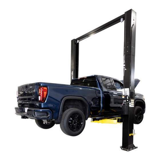
- Page 1 Installation, Operation & Maintenance Manual Two Post Surface Mounted Lift CL12A ODEL 12,000 APACITY 3000 2311 South Park Rd, Louisville, Kentucky 40219 Email: Web site: sales@challengerlifts.com www.challengerlifts.com Office 800-648-5438 502-625-0700 Fax 502-587-1933 IMPORTANT: READ THIS MANUAL COMPLETELY BEFORE INSTALLING or OPERATING LIFT...
- Page 2 Model CL12A Installation, Operation and Maintenance – ENERAL PECIFICATIONS (CL12A- CL12A- -QC) TANDARD AND UICK YCLE HT AND CL12A-LC CL12A CL12A-1 CL12A-2 See Figure 1 (-6”) (MAX) (-6”) (MAX) (-6”) (MAX) 143” 158” 164” 170” 176” 182” 188” Column Height [11’-11”]...
- Page 3 Model CL12A Installation, Operation and Maintenance Safety decals similar to those shown here are found ERTICAL LEARANCE on a properly installed lift. Be sure that all safety Check the height of the area where the lift is to be decals have been correctly installed. Verify that all installed.
-
Page 4: Installation
Model CL12A Installation, Operation and Maintenance ECEIVING NSTALLATION The shipment should be thoroughly inspected as soon MPORTANT Always wear safety glasses while installing lift. as it is received. The signed bill of lading is OOLS MINIMUM REQUIRED acknowledgement by the carrier of receipt in good a. - Page 5 Model CL12A Installation, Operation and Maintenance 6) Determine the sheave location on the lower bracket based on the overall height and width of the lift at its chosen configuration. Use the General Specifications table from page 2 and Fig 2 below.
- Page 6 Note: the column extensions are adjustable by used to connect both ends of the Long 3/8 OD 6” except for the CL12A-LC. Spring act as chain links. Feed one end of the D- Ring through both items and squeeze the link closed with pliers until ends overlap as shown.
- Page 7 Model CL12A Installation, Operation and Maintenance 25) Tighten Power Column anchors and recheck NCHORING column for plumb. Re-shim if necessary. Torque The anchor bolts must be installed at least 8” from to 150 foot pounds to set anchors. any crack, edge, or expansion joint. Recheck the area around both base plates.
- Page 8 Model CL12A Installation, Operation and Maintenance 29) Attach the Overhead Limit Switch to the rear set 30) Repeat for Idler Side – Attach the Idler Bracket of holes on the Power Side of the Overhead to the rear set of holes on the Idler Side of the...
- Page 9 37) Uncoil Power Column hose and loosely attach it to the hydraulic tee fitting ( ). Note: in hardware box CL12A-1 & CL12A-2 will require two extension hoses (supplied) to be attached to the tee Hydraulics fitting to extend the power column hose and to the power unit to extend the power unit hose.
- Page 10 Routing Diagram C in Fig 15. If installing and width. To make a loop, twist the hose. Loosely a CL12A-2 use the table in Fig 14 to determine connect the overhead hose to the other end of the the proper routing diagram A, B, OR C.
-
Page 11: Lock Release
Model CL12A Installation, Operation and Maintenance 42) Tighten the three hose fitting connections at the 49) B ERTAIN ITTINGS AND ONNECTIONS ARE Tee taking care not to twist or change the lay of IGHT T IS THE INSTALLERS RESPONSIBILITY TO any hose. -
Page 12: Arm Installation
Model CL12A Installation, Operation and Maintenance 53) Attach the Lower Mounting Tab to the idler column using the 5/16-18 x 3/8 long Phillips pan head screw. Rotate slightly to be in-line with connection to lock pawl as shown in Fig. 18b. -
Page 13: Safety Decal Placement
Model CL12A Installation, Operation and Maintenance DAPTER NSTALLATION AFETY ECAL LACEMENT 63) Locate the two pre-drilled holes on the back of 64) Clean surface of the rear column above the power each column 19” up from the top of the base plate unit and install Safety Decals, Page 3 and Fig. - Page 14 Model CL12A Installation, Operation and Maintenance INAL DJUSTMENTS ARM PIN KEEPER INSTALL 81) Install the arm pin into the arm assembly and YDRAULICS carriage. 68) Lower the lift to the floor and raise the lift 82) Raise lift high enough to gain access underneath approximately one foot.
-
Page 15: Wiring Diagram
Model CL12A Installation, Operation and Maintenance Wiring Diagram FOR SINGLE PHASE FIELD CONECTIONS (Normally Open) FIELD CONECTIONS FOR THREE PHASE FACTORY WIRED FOR 208−240V RECONNECTIONS FOR 440−480V Fig. 23 – Electrical Wiring Diagram Page 15 Rev. 01/23/2023 CL12-IOM-A.doc... -
Page 16: Operation Procedure
Model CL12A Installation, Operation and Maintenance American National Standard for Automotive Lifts- PERATION ROCEDURE Safety Requirements for Operation, Inspection and Maintenance; and in the case of frame AFETY OTICES AND ECALS engaging lift, ALI/LP-GUIDE, Vehicle Lifting This product is furnished with graphic safety... -
Page 17: Lifting A Vehicle
If the vehicle Check adapters for damage or excessive wear. seems unstable, lower the lift and readjust the Replace as required with genuine Challenger Lifts arms. If the vehicle is stable, raise the vehicle to a parts. -
Page 18: Parts Breakdown
ZIP TIE 3 1/2" Lg. (FOR LOCK RELEASE CABLE) Replace all worn, damaged, or broken parts with parts approved by Challenger Lifts Inc. or with parts meeting Challenger Lifts Inc. specifications. Contact your local Challenger Lifts Parts Distributor for pricing and availability. - Page 19 STACK ADAPTER EXTENSION – 3” B2206-6 STACK ADAPTER EXTENSION – 6” Replace all worn, damaged, or broken parts with parts approved by Challenger Lifts Inc. or with parts meeting Challenger Lifts Inc. specifications. Contact your local Challenger Lifts Parts Distributor for pricing and availability.
-
Page 20: Fig C. Hydraulics
1/4"-20 x 3/4” HEX FLANGE NUT 40085 1/4”-20 HEX FLANGE NUT Replace all worn, damaged, or broken parts with parts approved by Challenger Lifts Inc. or with parts meeting Challenger Lifts Inc. specifications. Contact your local Challenger Lifts Parts Distributor for pricing and availability. -
Page 21: Fig D. Synchronizer
12803-2 SYNC. CABLE ASSEMBLY (CL12-2) (Set of 2) Replace all worn, damaged, or broken parts with parts approved by Challenger Lifts Inc. or with parts meeting Challenger Lifts Inc. specifications. Contact your local Challenger Lifts Parts Distributor for pricing and availability. - Page 22 X10-088 M8 x 1.25 x 30mm SHCS Replace all worn, damaged, or broken parts with parts approved by Challenger Lifts Inc. or with parts meeting Challenger Lifts Inc. specifications. Contact your local Challenger Lifts Parts Distributor for pricing and availability.
- Page 23 Model CL12A Installation, Operation and Maintenance REVISIONS Page 23 Rev. 01/23/2023 CL12-IOM-A.doc...
Need help?
Do you have a question about the CL12A and is the answer not in the manual?
Questions and answers