Table of Contents
Advertisement
Installation, Operation &
Maintenance Manual
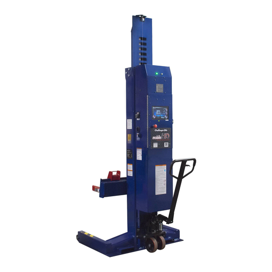
CLHM-140, CLHM-190, & CLHM-190W
W
P
L
S
IRELESS
ORTABLE
IFT
YSTEM
2311 South Park Rd. Louisville, Kentucky 40219
Email:
Web site:
sales@challengerlifts.com
www.challengerlifts.com
/
Office 800-648-5438
502-625-0700 Fax 502-587-1933
IMPORTANT:
READ THIS MANUAL COMPLETELY BEFORE
INSTALLING or OPERATING LIFT
Advertisement
Table of Contents


Need help?
Do you have a question about the CLHM-190 and is the answer not in the manual?
Questions and answers