Challenger Lifts Versymmetric CL10 Series Installation, Operation & Maintenance Manual
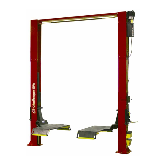
Two post surface mounted lift
Hide thumbs
Also See for Versymmetric CL10 Series:
- Installation, operation & maintenance manual (24 pages) ,
- Installation & operation manual supplement (7 pages) ,
- Installation, operation & maintenance manual (24 pages)
Table of Contents
Advertisement
Installation, Operation & Maintenance Manual
V
Email:
Office 800-648-5438
IMPORTANT:
ersymmetric®
Surface Mounted Lift
M
ODEL
10,000
2500
2311 South Park Rd Louisville, Kentucky 40219
sales@challengerlifts.com
/
502-625-0700 Fax 502-587-1933
READ THIS MANUAL COMPLETELY BEFORE
INSTALLING or OPERATING LIFT
Two Post
CL10
. C
LBS
APACITY
.
A
LBS
PER
RM
Web site:
www.challengerlifts.com
Rev. 12/04/18
Advertisement
Table of Contents

Subscribe to Our Youtube Channel
Related Manuals for Challenger Lifts Versymmetric CL10 Series


Summary of Contents for Challenger Lifts Versymmetric CL10 Series
- Page 1 Installation, Operation & Maintenance Manual ersymmetric® Two Post Surface Mounted Lift CL10 ODEL 10,000 APACITY 2500 2311 South Park Rd Louisville, Kentucky 40219 Email: Web site: sales@challengerlifts.com www.challengerlifts.com Office 800-648-5438 502-625-0700 Fax 502-587-1933 IMPORTANT: READ THIS MANUAL COMPLETELY BEFORE INSTALLING or OPERATING LIFT Rev.
-
Page 2: Specifications
Model CL10 Installation, Operation and Maintenance ENERAL PECIFICATIONS See Figure 1 CL10 CL10-2 CL10-3 11’- 8” 13’- 8” 14’- 8” Column Height 11’- 2 1/2 ” 13’- 2 1/2” 14’- 2 1/2” Floor to Overhead Switch 74 1/8” Rise Height (Screw Pads Highest Position) 11’- 11”... -
Page 3: Vertical Clearance
Model CL10 Installation, Operation and Maintenance ERTICAL LEARANCE EAD ENTIRE MANUAL BEFORE ASSEMBLING INSTALLING OPERATING OR SERVICING THIS Check the height of the area where the lift is to be EQUIPMENT installed. Clearance should be calculated based on ROPER MAINTENANCE AND INSPECTION IS the full raised height of the lift. -
Page 4: Installation
5/16” allen wrench shorted or damaged goods. Do this for your own protection. g. Needle nose pliers h. Hammer drill with 3/4” diameter carbide tipped Challenger Lifts NOTIFY AT ONCE if any bits hidden loss or damage is discovered after receipt. - Page 5 Model CL10 Installation, Operation and Maintenance 4) Install Power Column locking pawl and lock VERHEAD release clevis with 5/8” diameter x 1 1/2” lg 13) Before raising overhead into position install 4 shoulder bolt and 1/2”-13 nylon lock nut, Fig. 2. each (2 per column) hex flange bolts and nuts Attach 3/8”...
- Page 6 Model CL10 Installation, Operation and Maintenance Idler Bracket. The narrow slot needs to be YNCHRONIZER ABLES facing towards the Power Column. Slide the 18) Attach one end of synchronizing cable to Shutoff Bar over the limit switch on the Power carriage with the supplied nut and jam nut.
- Page 7 Model CL10 Installation, Operation and Maintenance & H OWER YDRAULIC OSES POWER UNIT HOSE 'O' RING ELBOW Fig 7 – Power Unit Mounting IMPORTANT – To insure proper hose fitting seal without damage to the fitting follow this Fig 8b – Hose Routing, procedure for each hose connection: Screw Power Side Column Ext.
-
Page 8: Arm Installation
Model CL10 Installation, Operation and Maintenance 29) Insert threaded sleeve portion cable assembly in slot located on tab above locking pawl, Fig 10. One jam nut should be located on each side of tab. Position threaded sleeve with ½” of thread below tab as indicated in Fig 10 and tighten jam nuts. -
Page 9: Safety Decals
Model CL10 Installation, Operation and Maintenance INAL DJUSTMENTS YDRAULICS 44) Lower the lift to the floor and raise the lift approximately one foot. 45) Start with Idler side first. Slowly and carefully loosen the bleed plug on top of the cylinder just enough to allow the entrapped air to escape. - Page 10 Model CL10 Installation, Operation and Maintenance EMALE NSTALL (3-S TAGE ARMS ONLY 57) Extend the arm fully and lift up on the male portion, Fig 15. 58) Using a hammer to set, place the shim on the mouth of the female arm. Use the provided self locking set screw and 1/8”...
-
Page 11: Wiring Diagram
Model CL10 Installation, Operation and Maintenance Wiring Diagram FOR SINGLE PHASE FIELD CONECTIONS (Normally Open) FIELD CONECTIONS FOR THREE PHASE FACTORY WIRED FOR 208−240V RECONNECTIONS FOR 440−480V Fig 13 – Electrical Wiring Diagram Page 11 Rev 12/04/18 CL10-IOM-A.doc... -
Page 12: Operation Procedure
Model CL10 Installation, Operation and Maintenance National Standard for Automotive Lifts-Safety PERATION ROCEDURE Requirements Operation, Inspection AFETY OTICES AND ECALS Maintenance; and in the case of frame engaging lift, ALI/LP-GUIDE, Vehicle Lifting Points/Quick This product is furnished with graphic safety Reference Guide for Frame Engaging Lifts;... - Page 13 Model CL10 Installation, Operation and Maintenance IFTING A EHICLE OSS OF POWER 1) Insure that the lifting arms are parked, out to full If for any reason the lift will not raise off the locks drive thru position. or the locks will not retract, consult factory authorized personnel.
-
Page 14: Maintenance
Replace required with genuine Challenger Lifts parts. Check synchronizer cable tension per Installation Instructions. Adjust if necessary. If both threaded ends of either cable have run out of adjustment, then replace both cables. (Cables should always be replaced in sets.) Monthly ... -
Page 15: Parts Breakdown
A2159 3/8-16NC x 3”Lg HEX HEAD C.S. Gr.5 Replace all worn, damaged, or broken parts with parts approved by Challenger Lifts Inc. or with parts meeting Challenger Lifts Inc. specifications. Contact your local Challenger Lifts Parts Distributor for pricing and availability. -
Page 16: Fig B. Lock
36096 BALL HANDLE – Power side ONLY Replace all worn, damaged, or broken parts with parts approved by Challenger Lifts Inc. or with parts meeting Challenger Lifts Inc. specifications. Contact your local Challenger Lifts Parts Distributor for pricing and availability. -
Page 17: Fig C. Hydraulics
5/16-18 x 1 HEX FLANGE HEAD BOLT 4100237 5/16 HEX FLANGE NUT Replace all worn, damaged, or broken parts with parts approved by Challenger Lifts Inc. or with parts meeting Challenger Lifts Inc. specifications. Contact your local Challenger Lifts Parts Distributor for pricing and availability. -
Page 18: Fig D. Synchronizer
A2158 1/4 DIA. x 1 3/4" Lg CLEVIS PIN Replace all worn, damaged, or broken parts with parts approved by Challenger Lifts Inc. or with parts meeting Challenger Lifts Inc. specifications. Contact your local Challenger Lifts Parts Distributor for pricing and availability. - Page 19 PARTS BREAKDOWN (continued) Fig E. Carriage & 3-Stage Arm Pack (B2202SD) Replace all worn, damaged, or broken parts with parts approved by Challenger Lifts Inc. or with parts meeting Challenger Lifts Inc. specifications. Contact your local Challenger Lifts Parts Distributor for pricing and availability.
- Page 20 B2204SD REAR ARM ASSY. Items: 73-93,100,101 Replace all worn, damaged, or broken parts with parts approved by Challenger Lifts Inc. or with parts meeting Challenger Lifts Inc. specifications. Contact your local Challenger Lifts Parts Distributor for pricing and availability. (Call Challenger Lifts Inc. (502) 625-0700 for the Parts Distributor in your area)
- Page 21 B2302SD ARM PACK, CL10, 2/3-STAGE (items 105-117) Replace all worn, damaged, or broken parts with parts approved by Challenger Lifts Inc. or with parts meeting Challenger Lifts Inc. specifications. Contact your local Challenger Lifts Parts Distributor for pricing and availability.
- Page 22 Model CL10 Installation, Operation and Maintenance NOTES Page 22 Rev 12/04/18 CL10-IOM-A.doc...
Need help?
Do you have a question about the Versymmetric CL10 Series and is the answer not in the manual?
Questions and answers