Table of Contents
Advertisement
Quick Links
Advertisement
Table of Contents

Subscribe to Our Youtube Channel
Related Manuals for Technogym Total Trunk


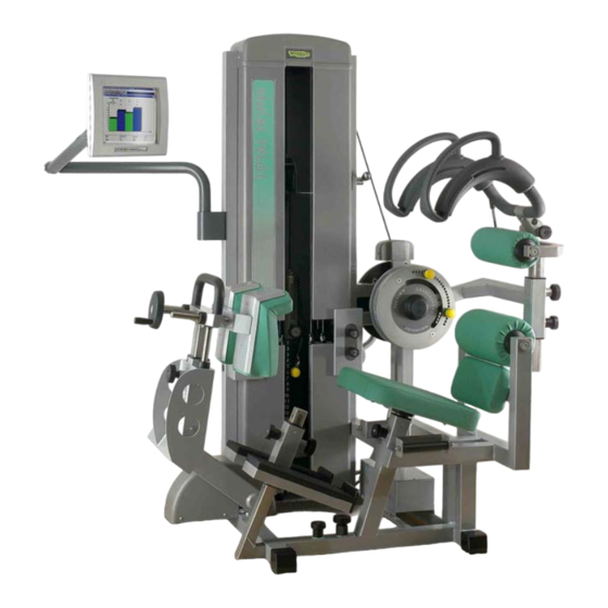
Summary of Contents for Technogym Total Trunk
- Page 1 & ERVICE MAINTENANCE MANUAL . 1.5...
- Page 3 The information contained in this document is subject to change without notice. Technogym does not guarantee this documentation in any way. Technogym shall not be held responsible for any errors contained in this manual and declines all liability for accidents or damages resulting from the supply, characteristics or use of this manual.
-
Page 5: Table Of Contents
Total Trunk: Service & Maintenance Manual - rev. 1.5 Contents 1. GENERAL NOTICES............................1.1 1.1............................... 1.1 NTRODUCTION 1.2............................1.1 ECOMMENDATIONS 1.3..................... 1.2 ENERAL RULES FOR REPAIR PROCEDURES 2. TECHNICAL CHARACTERISTICS........................2.1 2.1........................2.1 ECHANICAL CHARACTERISTICS 2.2. - Page 6 Total Trunk: Service & Maintenance Manual - rev. 1.5 7. DISASSEMBLY OF COMPONENTS......................... 7.1 7.1......................7.1 ISASSEMBLING THE ELECTRONICS BOX 7.2........................7.3 ISASSEMBLING THE ENCODER 7.3........................7.5 ISASSEMBLING THE LOAD CELL 7.4........................7.6 ISASSEMBLING THE THIGH REST 7.5.
- Page 7 Total Trunk: Service & Maintenance Manual - rev. 1.5 10.3.6. Checking the wiring and connections....................10.4 10.3.7. Replacing the cables........................10.4 10.3.8. Checking the clamping of screws and bolts..................10.5 10.3.9. Checking the play of the linkages ....................10.5 10.3.10. Checking the weight stack cross alignment..................10.5 11.
- Page 8 Total Trunk: Service & Maintenance Manual - rev. 1.5 Page intentionally left blank Page iv...
-
Page 9: General Notices
1.1. INTRODUCTION This document is reserved for Technogym Service technicians, and is intended to provide authorized personnel with the necessary information to correctly carry out repairs and maintenance. A thorough knowledge of the technical information contained in this manual is essential for completing the professional training of the operator. -
Page 10: General Rules For Repair Procedures
1. Always mark any parts or positions which may be confused with each other at the time of reassembly. 2. Use original Technogym spare parts and lubricants of the recommended brands. 3. Use special tools where specified. 4. Consult the Technical Newsletters, which may contain more up-to-date information on adjustments and maintenance than those contained in this manual. -
Page 11: Technical Characteristics
Total Trunk: Service & Maintenance Manual - rev. 1.5 2. TECHNICAL CHARACTERISTICS 2.1. MECHANICAL CHARACTERISTICS Width 110 cm Length (minimum) 115 cm Length (during exercise) 180 cm Height 182 cm Weight 325 Kg 2.2. ELECTRICAL CHARACTERISTICS Mains voltage 230 VAC... -
Page 12: Wiring Diagram
Total Trunk: Service & Maintenance Manual - rev. 1.5 2.5. WIRING DIAGRAM Reference Characteristics Dimensions Ferrite 1 209 Ohm 100 MHz Length: 32 mm; int. diameter: 10 mm; ext. diameter: 21 mm Ferrite 2 234 Ohm 100 MHz Length: 32 mm; int. diameter: 13 mm; ext. diameter: 29 mm... -
Page 13: Principles Of Operation
Total Trunk: Service & Maintenance Manual - rev. 1.5 3. PRINCIPLES OF OPERATION 3.1. BLOCK DIAGRAM The block diagram of the machine is shown in the figure below: 3.1.1. NCODER This component is fixed to the flange on the inner side of the machine and is used for detecting the movement performed by the user during the exercise. -
Page 14: Load Cell
Total Trunk: Service & Maintenance Manual - rev. 1.5 3.1.2. OAD CELL The load cell is a torque transducer constructed from 4 resistors connected in a Wheatstone bridge configuration. This device is fixed to the flange on the outer side and serves as a joint between the flange itself and the support of the counterweight. -
Page 15: Accessories
Total Trunk: Service & Maintenance Manual - rev. 1.5 4. ACCESSORIES 4.1. USB PEN DRIVE If the machine is equipped with PC, a 64MB Pen drive is also supplied, which may be connected by USB port. This is useful whenever you need to back up data or transfer data from the Ellipse PC mounted on one machine to another. -
Page 16: A0000054 - Pc With Bracket Arm
Total Trunk: Service & Maintenance Manual - rev. 1.5 4.3. A0000054 - PC WITH BRACKET ARM If the machine is supplied equipped with this accessory, the bracket arm will come already assembled on the machine. If, on the other hand, the PC bracket arm is fitted subsequently, follow the installation procedure below: 1. - Page 17 Total Trunk: Service & Maintenance Manual - rev. 1.5 5. Insert the two screws c from the inner side of the frame and the plastic shim d from the outer side. 6. Take the bracket arm and, to occupy less...
- Page 18 Total Trunk: Service & Maintenance Manual - rev. 1.5 10. Reassemble the connector of the serial cable 11. Insert the wires inside the electrical box through the hole on its side. 12. Fit the PC power supply h inside the electrical box.
-
Page 19: Installation Instructions
Total Trunk: Service & Maintenance Manual - rev. 1.5 5. INSTALLATION INSTRUCTIONS 5.1. SPECIFICATIONS AND REQUIREMENTS For correct installation of the machine, make sure that: 1. The machine is installed on a level surface that is free of vibrations and has sufficient carrying capacity for the combined weight of the machine and user. -
Page 20: First Power-On
To install the Technogym Measurement and Evaluation SW, proceed as follows: 1. Insert the diskette in the drive on the PC and start the setup program “Install.Exe”. 2. A dialog box appears in which it is possible to modify the default settings of the Technogym Measurement and Evaluation SW:... - Page 21 • The first field defines the source drive and path from which the installation data will be read. • The second field contains the default destination path “c:\WinDIGI”. The “Technogym Measurement and Evaluation SW” program is normally installed in this folder, but it is possible to choose a different drive or directory by typing in another path or by using the browse button on the right.
- Page 22 Total Trunk: Service & Maintenance Manual - rev. 1.5 Page intentionally left blank Pagina 5.4...
-
Page 23: Troubleshooting
Total Trunk: Service & Maintenance Manual - rev. 1.5 6. TROUBLESHOOTING The troubleshooting procedures are shown in the form of flow charts. In order to facilitate consultation, the following standard box shapes are used. This type of box is the START point of the troubleshooting procedure. It typically contains a description of the problem or malfunction. -
Page 24: The Pc Does Not Switch On
Total Trunk: Service & Maintenance Manual - rev. 1.5 6.1. THE PC DOES NOT SWITCH ON This error occurs when the power supply voltage does not reach the PC. Only for machines supplied with a PC . THE PC DOES... - Page 25 Total Trunk: Service & Maintenance Manual - rev. 1.5 Is the v oltage at the output of the Replace the power power inlet block correct? inlet block Check/replace the Is the v oltage at the input to the cable between the PC...
-
Page 26: The Machine Does Not Read The Data
Total Trunk: Service & Maintenance Manual - rev. 1.5 6.2. THE MACHINE DOES NOT READ THE DATA The possible causes are: THE MACHINE DOES NOT READ THE DATA IT DOES NOT READ ANY DATA IT DOES NOT READ THE LOAD CELL... -
Page 27: It Does Not Read Any Data
Total Trunk: Service & Maintenance Manual - rev. 1.5 6.2.1. T DOES NOT READ ANY DATA In this case the problem can be due to a variety of causes, most commonly the power supply and in the second place the communication between the PC and the components. Less frequently, it can happen that the two encoder and load cell sensors or the PC are defective. - Page 28 Total Trunk: Service & Maintenance Manual - rev. 1.5 Is the v oltage at the output of the Replace the power power inlet block correct? inlet block Check/replace the Is the v oltage at the input to the cable between the PC...
- Page 29 Total Trunk: Service & Maintenance Manual - rev. 1.5 Try replacing the bracket arm with all the cables. Does this Def ectiv e cables solv e the problem? Make sure that the serial cable connector is correctly Incorrect connection connected to the PC. Does this solv e the problem? Try replacing the PC.
- Page 30 Total Trunk: Service & Maintenance Manual - rev. 1.5 As for point (1) but with the tester probes across the input connector of the power supply. As for point (1) but with the tester probes across the output connector of the power supply.
-
Page 31: It Does Not Read The Load Cell Data
Total Trunk: Service & Maintenance Manual - rev. 1.5 6.2.2. T DOES NOT READ THE LOAD CELL DATA If the PC does not read the load cell data but only the encoder data, it means that the link between the PC and the components is functioning correctly, but there are problems with the part that handles the torque data: load cell and component interface box. -
Page 32: It Does Not Read The Encoder Data
Total Trunk: Service & Maintenance Manual - rev. 1.5 6.2.3. T DOES NOT READ THE ENCODER DATA If the PC does not read the encoder data but only the load cell data, it means that the link between the PC and the components is functioning correctly, but there are problems with the part that handles the displacement data: encoder and component interface box. -
Page 33: Difficulty Selecting The Weight Stack Plates
Total Trunk: Service & Maintenance Manual - rev. 1.5 6.3. DIFFICULTY SELECTING THE WEIGHT STACK PLATES In this case, the problem may be due to different causes: • Cable too taut; • Guide rods dirty. 6.3.1. ABLE TOO TAUT If the cable is too taut it may be difficult to select the desired weight load using the selector pin because the cable tension keeps the cross slightly lifted, causing its holes to become misaligned with those of the plates. -
Page 34: Problems Executing The Exercise
Total Trunk: Service & Maintenance Manual - rev. 1.5 6.4. PROBLEMS EXECUTING THE EXERCISE In this case, there can be a variety of causes: • Cable too loose; • Guide rods dirty; • Damaged latches. 6.4.1. ABLE TOO LOOSE If during the exercise it feels like there is no resistance during the first part of the movement, the weight stack cable may be too loose. -
Page 35: The Weight Doubling Mechanism Does Not Work
Total Trunk: Service & Maintenance Manual - rev. 1.5 6.5. THE WEIGHT DOUBLING MECHANISM DOES NOT WORK In this case, the problem may be due to a variety of causes: • Weight stack not in the rest position; • Weight stack cable too taut;... -
Page 36: Disk Image Backup Procedure
Total Trunk: Service & Maintenance Manual - rev. 1.5 6.6. DISK IMAGE BACKUP PROCEDURE This procedure creates a backup copy of the machine PC disk, which can be used in the Disaster Recovery procedure described in paragraph 6.7. “Disaster Recovery procedure“. -
Page 37: Disaster Recovery Procedure
Total Trunk: Service & Maintenance Manual - rev. 1.5 • Backup image file of the machine PC; • The file gost.exe which is found in the C:\bck folder of the machine PC; • The file restHD.bat which is found in the C:\bck folder of the machine PC;... -
Page 38: Backup And Restore Procedure
Total Trunk: Service & Maintenance Manual - rev. 1.5 This command restores the disk image backup to the machine PC. The restore process can last several minutes. At the end, a message indicates whether the command was successful. 13. Reboot the machine PC and disable the SOLID STATE DISK function previously enabled in step 2. -
Page 39: Disassembly Of Components
Total Trunk: Service & Maintenance Manual - rev. 1.5 7. DISASSEMBLY OF COMPONENTS 7.1. DISASSEMBLING THE ELECTRONICS BOX 1. Turn off the machine and unplug the mains lead from the wall outlet. 2. Back off the 2 screws a using a medium Phillips screwdriver. - Page 40 Total Trunk: Service & Maintenance Manual - rev. 1.5 Before closing the box, make sure that you have connected all earth cables on the machine, and test that they are grounded. Make sure the electrical cables are connected by checking the wiring diagrams in chap.
-
Page 41: Disassembling The Encoder
Total Trunk: Service & Maintenance Manual - rev. 1.5 7.2. DISASSEMBLING THE ENCODER 1. Carry out the procedure described in paragraph 7.1. “Disassembling electronics box“. 2. Unplug its connecting cable from the component interface box. 3. Back off the 4 screws a using a 4-mm Allen wrench. - Page 42 Total Trunk: Service & Maintenance Manual - rev. 1.5 7. Back off the grub screw f using a 2-mm Allen wrench. 8. Remove the encoder 9. To reassemble the encoder, carry out the above steps in reverse order. Figure 7.2-4...
-
Page 43: Disassembling The Load Cell
Total Trunk: Service & Maintenance Manual - rev. 1.5 7.3. DISASSEMBLING THE LOAD CELL 1. Carry out the procedure described in paragraph 7.1. “Disassembling electronics box“. 2. Unplug its connecting cable from the component interface box. 3. Back off the screws a using an 8-mm Allen wrench and remove the load cell b from its seat. -
Page 44: Disassembling The Thigh Rest
Total Trunk: Service & Maintenance Manual - rev. 1.5 7.4. DISASSEMBLING THE THIGH REST 1. Back off the screw a and the concealed screw indicated by the arrow, using a 19-mm wrench. Figure 7.4-1 2. Remove the entire thigh rest assembly b. -
Page 45: Disassembling The Gas Piston Of The Thigh Rest
Total Trunk: Service & Maintenance Manual - rev. 1.5 7.5. DISASSEMBLING THE GAS PISTON OF THE THIGH REST 1. Completely unscrew the knob a and remove the entire group b, lifting it upward. Figure 7.5-1 2. Unscrew the bolts c using two 12-mm wrenches, so as to be able to pull out the pin and remove the piston d. -
Page 46: Disassembling The Gas Piston Of The Pusher Mechanism
Total Trunk: Service & Maintenance Manual - rev. 1.5 7.6. DISASSEMBLING THE GAS PISTON OF THE PUSHER MECHANISM 1. Remove the plastic cap underneath which is the nut b shown in Figure 7.6-2 Figure 7.6-1 2. Back off the nut b using a 13-mm wrench to release the upper part of the gas piston. -
Page 47: Disassembling The Gas Piston Of The Seat
Total Trunk: Service & Maintenance Manual - rev. 1.5 7.7. DISASSEMBLING THE GAS PISTON OF THE SEAT 1. Back off the screw a with a 6-mm hex wrench, if necessary using a second wrench to hold in place the other screw on the opposite side of the roller. -
Page 48: Disassembling The Guards
Total Trunk: Service & Maintenance Manual - rev. 1.5 7.8. DISASSEMBLING THE GUARDS 1. Back off the screws a using a medium Phillips screwdriver and remove the upper part of the guards. Figure 7.8-1 2. Back off the 16 screws b, 8 on the right side and 8 on the left side, using a T25 torx wrench, and remove the rear machine guard. - Page 49 Total Trunk: Service & Maintenance Manual - rev. 1.5 3. Back off the 4 screws c in the inner part of the front left guard using an 8-mm wrench and repeat the operation on the right hand side. Figure 7.8-3 4.
- Page 50 Total Trunk: Service & Maintenance Manual - rev. 1.5 5. To disassemble the lower front guards it is necessary to select plate number 7 on the weight stack and lock the arm in the position shown in the figure at left, using the range of motion limiter pins.
-
Page 51: Disassembling The Elastic Bands
Total Trunk: Service & Maintenance Manual - rev. 1.5 7.9. DISASSEMBLING THE ELASTIC BANDS 1. Carry out the procedure described in paragraph 7.8. “Disassembling the guards“. 2. Rotate the selection knob of the elastic band that is being replaced to position 1. - Page 52 Total Trunk: Service & Maintenance Manual - rev. 1.5 4. Pull out the pin b and remove the elastic band. 5. To reassemble the elastic band, carry out the above steps in reverse order. Figure 7.9-3 Pagina 7.14...
-
Page 53: Disassembling The Weight Stack Cable
Total Trunk: Service & Maintenance Manual - rev. 1.5 7.10. DISASSEMBLING THE WEIGHT STACK CABLE 1. Carry out the procedure described in paragraph 7.8. “Disassembling the guards“. 2. Adjust the easy start selector to the end of exercise position (as shown in the figure) so that the stop a comes away from the component b. - Page 54 Total Trunk: Service & Maintenance Manual - rev. 1.5 4. Select position 1 on the weight doubling mechanism. 5. Remove the counterweight from its seat. 6. Back off all three grub screws e, using a 4- mm Allen wrench, so as to release the cable.
-
Page 55: Disassembling The Flange Cable
Total Trunk: Service & Maintenance Manual - rev. 1.5 7.11. DISASSEMBLING THE FLANGE CABLE 1. Carry out the procedure described in paragraph 7.8. “Disassembling the guards“. 2. Back off the two screws a using a 4-mm Allen wrench and lift up the plastic cover. - Page 56 Total Trunk: Service & Maintenance Manual - rev. 1.5 6. Pull out the cable, taking care with bearing e which must then be re-inserted if the cable is replaced. 7. To reassemble the cable, carry out the above steps in reverse order.
-
Page 57: Disassembling The Doubling Mechanism Cable
Total Trunk: Service & Maintenance Manual - rev. 1.5 7.12. DISASSEMBLING THE DOUBLING MECHANISM CABLE 1. Carry out the procedure described in paragraph 7.8. “Disassembling the guards“. 2. Select position 1 on the doubling mechanism, back off nut a with a 17-mm wrench to release the cable. - Page 58 Total Trunk: Service & Maintenance Manual - rev. 1.5 4. Pull the cable out from hole c, to which it is fixed by means of a knot. To reassemble the cable, carry out the above steps in reverse order. After completing this procedure, adjust the cable tension as described in paragraph 8.3.
-
Page 59: Disassembling The Counterweight
Total Trunk: Service & Maintenance Manual - rev. 1.5 7.13. DISASSEMBLING THE COUNTERWEIGHT 1. To disassemble the counterweight a, simply back off the screw b using a 6-mm Allen wrench. 2. To reassemble the counterweight carry out the above steps in reverse order and refer to the procedure “8.6. -
Page 60: Disassembling The Latch For Isometric Exercises
Total Trunk: Service & Maintenance Manual - rev. 1.5 7.14. DISASSEMBLING THE LATCH FOR ISOMETRIC EXERCISES 1. To disassemble the latch, simply back off the screws a using a 17-mm wrench. 2. To reassemble the counterweight carry out the above steps in reverse order and refer to the procedure 8.5. -
Page 61: Disassembling The Weight Stack
Total Trunk: Service & Maintenance Manual - rev. 1.5 7.15. DISASSEMBLING THE WEIGHT STACK 1. Carry out the procedures described in paragraphs 7.8. “Disassembling the guards“ and 7.10. “Disassembling the weight stack cable“. 2. On both sides, back off the two grub screws a at the base of the weight stack which secure the guide rod. -
Page 62: Disassembling The Pc
Total Trunk: Service & Maintenance Manual - rev. 1.5 7.16. DISASSEMBLING THE PC 1. Turn off the machine and unplug the mains lead from the wall outlet. 2. Disconnect the 4 cables which reach the PC from the bracket arm. -
Page 63: Disassembling The Pc Bracket Arm
Total Trunk: Service & Maintenance Manual - rev. 1.5 7.17. DISASSEMBLING THE PC BRACKET ARM This operation should preferably be carried out by two people. 1. Carry out the procedure described in paragraph 7.1. “Disassembling electronics box“, up until the opening of the protection, and the procedure described in paragraph 7.16. - Page 64 Total Trunk: Service & Maintenance Manual - rev. 1.5 Page intentionally left blank Pagina 7.26...
-
Page 65: Adjustments
Total Trunk: Service & Maintenance Manual - rev. 1.5 8. ADJUSTMENTS 8.1. CABLE TENSION 1. Fix the flange cable to the cam using the grub screws a and check that it passes over the pulleys b and through the two pulleys c. - Page 66 Total Trunk: Service & Maintenance Manual - rev. 1.5 The tension must now be adjusted on the weight stack. 3. Position the easy start selector in the lowermost hole, resting on the first weight stack plate. 4. Select position 1 of the weight doubling lever and remove the counterweight from the cylinder d.
-
Page 67: Adjusting The Stop On The Weight Stack Cable
Total Trunk: Service & Maintenance Manual - rev. 1.5 8.2. ADJUSTING THE STOP ON THE WEIGHT STACK CABLE 1. Check that the weight stack cable tension is correctly adjusted as described in the paragraph 8.1. “Cable tension“. 2. The machine must be in the rest position and the weight doubling lever must be in position 3. -
Page 68: Adjusting The Weight Doubling Mechanism Cable
Total Trunk: Service & Maintenance Manual - rev. 1.5 8.3. ADJUSTING THE WEIGHT DOUBLING MECHANISM CABLE 1. Select position 2 of the weight doubling lever. 2. Back off the nut a which is used for adjusting the cable length. Figure 8.3-1 3. -
Page 69: Tension Of The Additional Weight Guide
Total Trunk: Service & Maintenance Manual - rev. 1.5 8.4. TENSION OF THE ADDITIONAL WEIGHT GUIDE 1. Back off the nut a using a 13-mm wrench and, turning screw b with a 6-mm Allen wrench, adjust the guide cable tension until it is taut. -
Page 70: Adjusting The Latch For Isometric Exercises
Total Trunk: Service & Maintenance Manual - rev. 1.5 8.5. ADJUSTING THE LATCH FOR ISOMETRIC EXERCISES 1. The latch can be adjusted both horizontally and vertically in the following way: • Vertical adjustment: back off the three screws a using a 17-mm wrench and... -
Page 71: Counterweight Position
Total Trunk: Service & Maintenance Manual - rev. 1.5 8.6. COUNTERWEIGHT POSITION 1. Lock the arm in the 35° position using the latch a. 2. Back off the screw b using a 6-mm Allen wrench and allow the counterweight to freely position itself under the action of gravity. -
Page 72: Bracket Arm Movement
Total Trunk: Service & Maintenance Manual - rev. 1.5 8.7. BRACKET ARM MOVEMENT 1. An initial adjustment of the motion of the PC bracket arm can be made by turning knob a clockwise or anticlockwise; if this is not sufficient, remove the plastic protection covering nut b and adjust the nut using a 15- mm wrench. -
Page 73: Machine Configuration
Total Trunk: Service & Maintenance Manual - rev. 1.5 9. MACHINE CONFIGURATION 9.1. CONFIGURING THE SW PARAMETERS The machine configuration is performed using the LEITSTAT program, which can be found in C:\service\Leitstat\leitstat.exe. After starting the program, the following window appears on the screen: Figure 9.1-1... -
Page 74: Selecting The Device
Total Trunk: Service & Maintenance Manual - rev. 1.5 Click the “Option” button; a dialog appears in which it is possible to set up the parameters as shown in the following figures. 9.1.1. ELECTING THE DEVICE Configure the device from which the PC will read the data as shown in the figure below: Figure 9.1-3... -
Page 75: Set Up The Encoder Parameters
Total Trunk: Service & Maintenance Manual - rev. 1.5 9.1.3. ET UP THE ENCODER PARAMETERS configure the encoder parameters as shown in the figure below: Figure 9.1-5 Pagina 9.3... -
Page 76: Protection Of Sw Parameters
Total Trunk: Service & Maintenance Manual - rev. 1.5 9.2. PROTECTION OF SW PARAMETERS It is possible to configure the machine so that the user is prevented from modifying any of the parameters. This protection is achieved by setting jumper J1, inside the component interface box shown in Figure 9.2-1, in the open position. -
Page 77: Configuring The Technogym Measurement And Evaluation Sw
The following procedure is used for changing the parameters of the file “WinDIGI.ini”. It is in any case possible to check these parameters against the file available from Technogym Direct. Start the program by clicking the desktop link; the following window will appear on the screen: Figure 9.3-1... - Page 78 Total Trunk: Service & Maintenance Manual - rev. 1.5 Enter the password “FERRARI” and confirm by clicking , after which the following dialog appears: Figure 9.3-3 Check that the data is correct and continue by clicking At this point a dialog appears with the various machine settings; check that they are the same as those in the figures below: Figure 9.3-4...
- Page 79 Total Trunk: Service & Maintenance Manual - rev. 1.5 The program will then display the following dialog: Figure 9.3-5 Check that the data shown in the dialog is the same as that in the figure above, and if this is the case click to continue.
- Page 80 Total Trunk: Service & Maintenance Manual - rev. 1.5 The program will then display the following dialog: Figure 9.3-7 Check once again that the data in the dialog is the same as that in the figure above, and if this is the case click to continue.
- Page 81 The program will then display the following dialog: Figure 9.3-9 Check all the parameter values against those in the figure above, entering the correct values if necessary. Click to finish the configuration procedure of the “Technogym Measurement and Evaluation SW” program. Pagina 9.9...
-
Page 82: Calibration Of The Load Cell
• Start the LEITSTAT program and proceed as described in paragraph 11.3. “Component tests”, checking that the correct value is detected when an object of known weight is rested on the arm. • Start the “Technogym Measurement and Evaluation SW” program and make sure it is in the “Isometric Test” session;... -
Page 83: Scheduled Maintenance
Total Trunk: Service & Maintenance Manual - rev. 1.5 10. SCHEDULED MAINTENANCE To keep the machine in perfect working order, it is necessary to carry out certain scheduled maintenance actions in order to forestall possible problems. There are essentially 3 types of maintenance operations: •... -
Page 84: Monthly Maintenance Operations
Total Trunk: Service & Maintenance Manual - rev. 1.5 10.2. MONTHLY MAINTENANCE OPERATIONS These operations can be carried out by the machine owner and do not require any special skills. The monthly maintenance operations involve simple cleaning and lubrication actions and checks on the state of wear, in order to ensure correct and safe operation of the machine. -
Page 85: Checking The Gas Pistons
Total Trunk: Service & Maintenance Manual - rev. 1.5 10.2.5. C HECKING THE GAS PISTONS 1. Check the functioning of the gas pistons, making sure there is adequate damping on the return of the rod to the fully extended position. -
Page 86: Twice-Yearly Maintenance Operations
TWICE-YEARLY MAINTENANCE OPERATIONS These operations can only be carried out by a qualified technician specifically trained by Technogym and authorized to carry out machine installation and adjustments, as well as special maintenance actions or repairs which require special knowledge of the machine, its operation, safety systems and working procedures. -
Page 87: Checking The Clamping Of Screws And Bolts
Total Trunk: Service & Maintenance Manual - rev. 1.5 10.3.8. C HECKING THE CLAMPING OF SCREWS AND BOLTS 1. Check that the screws and bolts are securely clamped, particularly those of the weight stack, seat adjustments and in general wherever there are moving parts. Lock down any loose components. - Page 88 Total Trunk: Service & Maintenance Manual - rev. 1.5 Page intentionally left blank Pagina 10.6...
-
Page 89: Functional Tests
11.1. ELECTRICAL SAFETY TEST Technogym ensures its own safety standards by means of the following tools and activities: • ISO 9001/2000 certification of the company; • certification of the device in compliance with medical regulations 60601-1 and 60601-1-2;... -
Page 90: Start-Up Check
Total Trunk: Service & Maintenance Manual - rev. 1.5 11.2. START-UP CHECK Following installation and after every technical intervention on the machine, plug it into a power outlet, set the power switch to ON and make sure that: • the green light comes on;... -
Page 91: Component Tests
Total Trunk: Service & Maintenance Manual - rev. 1.5 11.3. COMPONENT TESTS The machine tests are performed using the LEITSTAT program, which can be found in C:\service\Leitstat\leitstat.exe or by creating a link to “leitstat.exe” on the PC desktop. After starting the program, the following window appears on the screen: Figure 11.3-1... - Page 92 Total Trunk: Service & Maintenance Manual - rev. 1.5 Figure 11.3-3 The values displayed in the above dialog are: • torque: the first value indicates the torque exerted on the lever, expressed in Nm. • position: the second value gives the position of the lever expressed in degrees multiplied by 10.
-
Page 93: Weight Stack Cable Assembly Test
Total Trunk: Service & Maintenance Manual - rev. 1.5 11.4. WEIGHT STACK CABLE ASSEMBLY TEST Make sure the weight stack cable is properly assembled, ensuring that: • all grub screws of the cable clamp pins have been firmly tightened, selecting the maximum load and performing one or two repetitions;... -
Page 94: Housing Assembly Test
Total Trunk: Service & Maintenance Manual - rev. 1.5 11.9. HOUSING ASSEMBLY TEST Make sure the machine housing is properly assembled, checking that all guards have been mounted correctly, as described in the procedures in chapter 7 of this manual, so that no part of the machine remains unprotected and a possible cause of user accident and injury. -
Page 95: Appendix
12.1. LIST OF CRITICAL SPARE PARTS Technogym medical devices are identified by “Serial N” plates that allow them to be tracked throughout the useful life-span of the device. Just as for products, there is also a list of so-called “critical” components which, through the Serial N, must be guaranteed as traceable. -
Page 96: Tools To Be Used
Total Trunk: Service & Maintenance Manual - rev. 1.5 12.2. TOOLS TO BE USED The following tools are required for carrying out the various disassembly, adjustment and maintenance action on the machine: • Medium Phillips screwdriver; • Flat head screwdriver;... - Page 98 TECHNOGYM S.p.A. Via G. Perticari, 20 47035 Gambettola (FC) ITALIA Tel.: +39-0547-650438 Fax: +39-0547-650150 e-mail: service@technogym.com 0SM00128-ING...
Need help?
Do you have a question about the Total Trunk and is the answer not in the manual?
Questions and answers