Table of Contents

Related Manuals for Technogym PURESTRENGTH


Summary of Contents for Technogym PURESTRENGTH
- Page 1 & & . 4.1 (F . 2015)
- Page 3 The information contained in this document is subject to change without notice. Technogym does not guarantee this documentation in any way. Technogym shall not be held responsible for any errors contained in this manual and declines all liability for accidents or damages resulting from the supply, characteristics or use of this manual.
-
Page 5: Table Of Contents
PURESTRENGTH & BENCHES: Guida all'Assistenza Tecnica - rev. 4.1 Contents 1. GENERAL NOTICES ............................. 1.1 1.1. I ..............................1.1 NTRODUCTION 1.2. R ............................1.1 ECOMMENDATIONS 1.3. G ......................1.2 ENERAL RULES FOR REPAIR PROCEDURES 2. TECHNICAL CHARACTERISTICS ........................2.1 2.1. E ............................. - Page 6 PURESTRENGTH & BENCHES: Guida all'Assistenza Tecnica - rev. 4.1 5.3. D LEG PRESS (MG50) ...................... 5.19 ISASSEMBLING THE 5.3.1. Leg Press Guard ........................... 5.19 5.3.2. Disassembling the leg press easy start lever ..................5.20 5.3.3. Disassembling the leg press platform lever ..................5.21 5.4.
-
Page 7: General Notices
1. GENERAL NOTICES 1.1. INTRODUCTION This document is reserved for Technogym Service technicians, and is intended to provide authorized personnel with the necessary information to correctly carry out repairs and maintenance. A thorough knowledge of the technical information contained in this manual is essential for completing the professional training of the operator. -
Page 8: General Rules For Repair Procedures
1. Always mark any components or positions which may be confused with each other at the time of reassembly. 2. Use original Technogym spare parts and lubricants of the recommended brands. 3. Use special tools where specified. 4. Consult the Technical Newsletters, which may contain more up-to-date information on adjustments and maintenance than those contained in this manual. -
Page 9: Technical Characteristics
PURESTRENGTH & BENCHES: Guida all'Assistenza Tecnica - rev. 4.1 2. TECHNICAL CHARACTERISTICS 2.1. ENCODING EQUIPMENTS The PURESTRENGTH equipment code is a sequence of 12 alphanumeric characters arranged as follows: Characters Description Key to values 1,2, Equipment line MG = Purestrength Line... -
Page 10: Encoding Benches
PURESTRENGTH & BENCHES: Guida all'Assistenza Tecnica - rev. 4.1 2.2. ENCODING BENCHES The PURESTRENGTH benches code is a sequence of 10 alphanumeric characters arranged as follows: Characters Description Key to values 1,2, Equipment line PG = PureStrength Bench line 01 = Olympic Incline... -
Page 11: Ambient Specifications
PURESTRENGTH & BENCHES: Guida all'Assistenza Tecnica - rev. 4.1 2.3. AMBIENT SPECIFICATIONS Operating from 5° to 35°C Temperature Storage from -20 to 55°C Operating from 30% to 80% non-condensing Humidity Storage from 5% to 85% non-condensing 2.4. CONFORMITY TO REGULATIONS... -
Page 12: Mechanical Characteristics
PURESTRENGTH & BENCHES: Guida all'Assistenza Tecnica - rev. 4.1 2.6. MECHANICAL CHARACTERISTICS 2.6.1. E QUIPMENT HARACTERISTICS 2.6.1.1. MG05 Chest Press – Chest Press 1500mm x 1200mm x 1715mm Dimensions (L x W x H) x 47 x 67 ” ”... - Page 13 PURESTRENGTH & BENCHES: Guida all'Assistenza Tecnica - rev. 4.1 2.6.1.2. MG10 Wide Chest Press – Wide Chest Press 1450mm x 1182mm x 1730mm Dimensions (L x W x H) x 46 x 68 ” ” ” Overall weight 170Kg - 374lbs...
- Page 14 PURESTRENGTH & BENCHES: Guida all'Assistenza Tecnica - rev. 4.1 2.6.1.3. MG15 Incline Chest Press – Incline Chest Press 1540mm x 1030mm x 1685mm Dimensions (L x W x H) x 40 x 66 ” ” ” Equipment overall weight 160Kg - 353lbs...
- Page 15 PURESTRENGTH & BENCHES: Guida all'Assistenza Tecnica - rev. 4.1 2.6.1.4. MG20 Pulldown – Pulldown 1110mm x 1740mm x 1990mm Dimensions (L x W x H) x 68 x 78 ” ” ” Equipment overall weight 150Kg - 330lbs Maximum load...
- Page 16 PURESTRENGTH & BENCHES: Guida all'Assistenza Tecnica - rev. 4.1 2.6.1.5. MG25 Low Row – Low Row 1320mm x 1250mm x 1630mm Dimensions (L x W x H) x 49 x 64 ” ” ” Equipment overall weight 125Kg - 275lbs...
- Page 17 PURESTRENGTH & BENCHES: Guida all'Assistenza Tecnica - rev. 4.1 2.6.1.6. MG30 – 1190mm x 1380mm x 1300mm Dimensions (L x W x H) x 54 x 51 ” ” ” Equipment overall weight 135Kg - 297lbs Maximum load 200Kg - 441lbs...
- Page 18 PURESTRENGTH & BENCHES: Guida all'Assistenza Tecnica - rev. 4.1 2.6.1.7. MG35 Shoulder Press – Shoulder Press 1290mm x 1260mm x 1485mm Dimensions (L x W x H) x 50 x 58 ” ” ” Equipment overall weight 140Kg - 308lbs...
- Page 19 PURESTRENGTH & BENCHES: Guida all'Assistenza Tecnica - rev. 4.1 2.6.1.8. MG40 Rear Kick – Rear Kick 1115mm x 1330mm x 1650mm Dimensions (L x W x H) x 52 x 65 ” ” ” Equipment overall weight 140Kg - 308lbs...
- Page 20 PURESTRENGTH & BENCHES: Guida all'Assistenza Tecnica - rev. 4.1 2.6.1.9. MG45 Calf – Calf 1120mm x 1710mm x 1170mm Dimensions (L x W x H) x 67 x 46 ” ” ” Equipment overall weight 150Kg - 330lbs Maximum load...
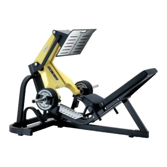
- Page 21 PURESTRENGTH & BENCHES: Guida all'Assistenza Tecnica - rev. 4.1 2.6.1.10. MG50 Leg Press – Leg Press 1780mm x 2060mm x 1525mm Dimensions (L x W x H) x 81 x 60 ” ” ” Equipment overall weight 215Kg - 474lbs...
- Page 22 PURESTRENGTH & BENCHES: Guida all'Assistenza Tecnica - rev. 4.1 2.6.1.11. MG55 Seated Dip – Seated Dip 1392mm x 1578mm x 966 mm Dimensions (L x W x H) x 62 x 38 ” ” ” Equipment overall weight 148 kg - 326 lbs...
- Page 23 PURESTRENGTH & BENCHES: Guida all'Assistenza Tecnica - rev. 4.1 2.6.1.12. MG60 - Biceps Biceps 1385mm x 1058mm x 1005 mm Dimensions (L x W x H) 54.5 x 41.7 x 40 ” ” ” Equipment overall weight 136kg - 300lbs...
- Page 24 PURESTRENGTH & BENCHES: Guida all'Assistenza Tecnica - rev. 4.1 2.6.1.13. MG65 Leg Extension – Leg Extension 1258mm x 1238mm x 1150 mm Dimensions (L x W x H) 49.5 x 49 x 45.3 ” ” ” Equipment overall weight 117kg 258lbs –...
- Page 25 PURESTRENGTH & BENCHES: Guida all'Assistenza Tecnica - rev. 4.1 2.6.1.14. MG70 Standing Leg Curl – Standing Leg Curl 1050mm x 1220mm x 1290 mm Dimensions (L x W x H) 41.3 x 48 x 51 ” ” ” Equipment overall weight...
- Page 26 PURESTRENGTH & BENCHES: Guida all'Assistenza Tecnica - rev. 4.1 2.6.1.15. MG75 Linear Leg Press – Linear Leg Press 1567mm x 2693mm x 1502 mm Dimensions (L x W x H) 61.7 x 106 x 59 ” ” ” Equipment overall weight...
-
Page 27: Benches Characteristics
PURESTRENGTH & BENCHES: Guida all'Assistenza Tecnica - rev. 4.1 2.6.2. B ENCHES HARACTERISTICS 2.6.2.1. PG01 Olympic Incline – Olympic Incline 1843mm x 1266mm x 1604mm Dimensions (L x W x H) x 49 x 63 ” ” ” Equipment overall weight... - Page 28 PURESTRENGTH & BENCHES: Guida all'Assistenza Tecnica - rev. 4.1 2.6.2.2. PG03 Adjust Decline / Abdominal – Adjust Decline / Ab crunch 1838 x 548 x 875mm Dimensions (L x W x H) 72 x 22 x 38in Equipment overall weight...
- Page 29 PURESTRENGTH & BENCHES: Guida all'Assistenza Tecnica - rev. 4.1 2.6.2.3. PG04 Adjustable – Adjustable 1330mm x 510mm x 1318mm Dimensions (L x W x H) x 20 x 52 ” ” ” Equipment overall weight 59Kg 130lbs – 1385mm x 560mm x 498mm Packaging Dimensions (L x W x H) 54.5...
- Page 30 PURESTRENGTH & BENCHES: Guida all'Assistenza Tecnica - rev. 4.1 2.6.2.4. PG05 Lower back – Lower Back 1197 x 760 x 920mm Dimensions (L x W x H) 47 x 30 x 36in Equipment overall weight 57Kg 126lbs – 1180mm x 720mm x 654mm Packaging Dimensions (L x W x H) 46.5...
- Page 31 PURESTRENGTH & BENCHES: Guida all'Assistenza Tecnica - rev. 4.1 2.6.2.5. PG06 Scott – Scott 1047mm x 822mm x 996mm Dimensions (L x W x H) x 32 x 39 ” ” ” Equipment overall weight 84Kg 185lbs – 1090mm x 850mm x 904mm Packaging Dimensions (L x W x H) x 33.5...
- Page 32 PURESTRENGTH & BENCHES: Guida all'Assistenza Tecnica - rev. 4.1 2.6.2.6. PG07 Olympic flat – Olympic Flat 1645mm x 1266mm x 1358mm Dimensions (L x W x H) x 49 x 53 ” ” ” Equipment overall weight 109Kg 240lbs –...
- Page 33 PURESTRENGTH & BENCHES: Guida all'Assistenza Tecnica - rev. 4.1 2.6.2.7. PG08 Olympic military – Olympic Military 1523mm x 1266mm x 1866mm Dimensions (L x W x H) x 49 x 73 ” ” ” Equipment overall weight 153Kg 337lbs –...
- Page 34 PURESTRENGTH & BENCHES: Guida all'Assistenza Tecnica - rev. 4.1 2.6.2.8. PG10 Olympic Half Rack – Olympic Half Rack 1406mm x 1260mm x 2363mm Dimensions (L x W x H) x 50 x 93 ” ” ” Equipment overall weight 210Kg 463lbs –...
- Page 35 PURESTRENGTH & BENCHES: Guida all'Assistenza Tecnica - rev. 4.1 2.6.2.9. PG11 Olympic Power Rack – The platform and the accessories are NOT included, the image is only representative. Power Rack 1300mm x 1673mm x 2455mm Dimensions (L x W x H)
- Page 36 PURESTRENGTH & BENCHES: Guida all'Assistenza Tecnica - rev. 4.1 2.6.2.10. PG14 - Flat Flat 510mm x 1187mm x 452mm Dimensions (L x W x H) x 47 x 18 ” ” ” Equipment overall weight 28Kg 62lbs – 1210mm x 330mm x 350mm Packaging Dimensions (L x W x H) 47.5...
- Page 37 PURESTRENGTH & BENCHES: Guida all'Assistenza Tecnica - rev. 4.1 2.6.2.11. PG23 Olympic Decline – Olympic Decline 1890mm x 1266mm x 1320mm Dimensions (L x W x H) x 49 x 52 ” ” ” Equipment overall weight 108Kg 238lbs –...
-
Page 39: Installing And Moving The Equipment
PURESTRENGTH & BENCHES: Guida all'Assistenza Tecnica - rev. 4.1 3. INSTALLING AND MOVING THE EQUIPMENT 3.1. INSTALLATION SPECIFICATIONS AND REQUIREMENTS For proper installation of the equipment, make sure that: 1. The equipment is installed on a level, vibration-free surface with a sufficient capacity to support its weight plus that of the user. -
Page 40: Equipment Installation
PURESTRENGTH & BENCHES: Guida all'Assistenza Tecnica - rev. 4.1 3.3. EQUIPMENT INSTALLATION CAUTION: For the installation procedures of all the equipment: refer to the User Manual and Installation Manual tool. 3.4. MOVING Take care to protect the frame when you are moving or lifting the equipment to avoid to damage it. -
Page 41: Equipment Fastening To The Ground
PURESTRENGTH & BENCHES: Guida all'Assistenza Tecnica - rev. 4.1 3.5. EQUIPMENT FASTENING TO THE GROUND The hole in the frame of the equipment is Ø10mm. 1. Remove the caps and mark the position on the ground with a marker; 2. Drill the holes on the marks;... -
Page 42: Power
PURESTRENGTH & BENCHES: Guida all'Assistenza Tecnica - rev. 4.1 3.6. POWER RACK FASTENING TO THE GROUND (PG11) The hole in the frame of the tool is Ø13mm. 1. Drill holes in the floor as shown in figure; 2. Position the tool at the holes;... -
Page 43: Accessories
PURESTRENGTH & BENCHES: Guida all'Assistenza Tecnica - rev. 4.1 4. ACCESSORIES 4.1. A0000356-XX: PLATE RACK The code must be complemented with the colour variation (-XX) Plate Rack 670mm x 670mm x 1145mm Dimensions (L x W x H) x 50 x 58 ”... -
Page 44: A0000374: Plate Holder Kit With 2 Pins
PURESTRENGTH & BENCHES: Guida all'Assistenza Tecnica - rev. 4.1 4.2. A0000374: PLATE HOLDER KIT WITH 2 PINS The kit contains 2 pins and the components needed to install them on the equipment. Plate Rack Kit Compatible Equipment MG050 Chest Press no. -
Page 45: A0000363: Plate Rack Kit With 1 Pin
PURESTRENGTH & BENCHES: Guida all'Assistenza Tecnica - rev. 4.1 4.3. A0000363: PLATE RACK KIT WITH 1 PIN The kit contains 1 pin and the components needed to install them on the equipment. Plate Rack Kit Compatible Equipment MG050 Chest Press no. -
Page 46: A0000398-Xx: Plate Support Accessory
PURESTRENGTH & BENCHES: Guida all'Assistenza Tecnica - rev. 4.1 4.4. A0000398-XX: PLATE SUPPORT ACCESSORY The code must be complemented with the colour variation (-XX) Plate Rack 1345mm x 550mm x 438mm Dimensions (L x W x H) x 22 x 17.5 ”... -
Page 47: A0000447-Xx: Connect Adjustable Rack
PURESTRENGTH & BENCHES: Guida all'Assistenza Tecnica - rev. 4.1 4.5. A0000447-XX: CONNECT ADJUSTABLE RACK The code must be complemented with the colour variation (-XX) Plate Rack 1015mm x 320mm x 120mm Dimensions (L x W x H) x 12.5 x 4.7 ”... -
Page 48: A0000520-Xx: Barbell Holder Rack (10 Seats)
PURESTRENGTH & BENCHES: Guida all'Assistenza Tecnica - rev. 4.1 4.6. A0000520-XX: BARBELL HOLDER RACK (10 SEATS) The code must be complemented with the colour variation (-XX) It can be used only with pre-loaded barbells (Code BA-XX). 10 Place Barbel Rack... -
Page 49: A0000521-Xx: Handlebar Holder Rack (10 Pairs)
PURESTRENGTH & BENCHES: Guida all'Assistenza Tecnica - rev. 4.1 4.7. A0000521-XX: HANDLEBAR HOLDER RACK (10 PAIRS) The code must be complemented with the colour variation (-XX) Two Tier Dumbbell Rack 667mm x 2522mm x 749mm Dimensions (L x W x H) - Page 50 PURESTRENGTH & BENCHES: Guida all'Assistenza Tecnica - rev. 4.1 4.7.1. ACCESSORIES - PG11 Accessories PG11 Corner Weight Storage Reinforcement (x2) CODE A0000774 CODE A0000827 Barbell Pivot Bands Attachment (single) (image not available) CODE A0000780 CODE A0000781 Multigrip Dip Handles Toast Disc Rack...
- Page 51 PURESTRENGTH & BENCHES: Guida all'Assistenza Tecnica - rev. 4.1 Technique Boxes Foldable Foot plates (pair) (x4) CODE A0000825 CODE A0000817 External J Hook Support Barbell Storage (pair) (pair) CODE A0000808 CODE A0000806 Stand Alone Platform CODE A0000759 Page 4.9...
- Page 52 PURESTRENGTH & BENCHES: Guida all'Assistenza Tecnica - rev. 4.1 Platform for Power Rack CODE A0000760 Platform for Half Rack CODE A0000761 Page 4.10...
-
Page 53: Disassembling Components
PURESTRENGTH & BENCHES: Guida all'Assistenza Tecnica - rev. 4.1 5. DISASSEMBLING COMPONENTS 5.1. DISASSEMBLING COMMON TO SEVERAL EQUIPMENT 5.1.1. S EAT ADJUSTMENT SYSTEM 1. Unscrew the 4 screws (a) using a 17mm wrench. 2. Remove the seat. Figure 5.1-1 3. Unscrew the 2 screws (b) using a Phillips screwdriver. - Page 54 PURESTRENGTH & BENCHES: Guida all'Assistenza Tecnica - rev. 4.1 4. Remove the guard by pulling it up out of its lower seats. 5. To remove the pin (c) from the spring, force the side walls of the guard slightly outward.
-
Page 55: Disassembling The Handles
PURESTRENGTH & BENCHES: Guida all'Assistenza Tecnica - rev. 4.1 9. To replace the front seat adjustment support, unscrew the 2 screws (g) using a 6mm hexagonal key. 10. To replace the rear support, remove the 6 rivets (h). To reassemble the removed parts, carry out the disassembling steps in reverse order. - Page 56 PURESTRENGTH & BENCHES: Guida all'Assistenza Tecnica - rev. 4.1 5.1.3. D ISASSEMBLING THE HANDLES 1. Remove the handle end by unscrewing the screw (a) with a 6mm hexagonal key. 2. Pull out the handle. To reassemble the removed parts, carry out the disassembling steps in reverse order.
-
Page 57: Upholstery
PURESTRENGTH & BENCHES: Guida all'Assistenza Tecnica - rev. 4.1 5.1.4. U PHOLSTERY Disassemble guard described paragraph 5.3. Disassembling the LEG PRESS “ (MG50) Leg Press Guard ” 1. Unscrew the 3 screws (a) using a 17mm wrench. 2. Remove the backrest (b). -
Page 58: Disassembling The Easy-Start Lever Spring
PURESTRENGTH & BENCHES: Guida all'Assistenza Tecnica - rev. 4.1 5.1.6. D ISASSEMBLING THE EASY START LEVER SPRING For this operation, the lever must be raised so that the tension on the spring is released. 1. Remove the snap rings (a) from either side. -
Page 59: Disassembling The Levers
PURESTRENGTH & BENCHES: Guida all'Assistenza Tecnica - rev. 4.1 5.1.7. D ISASSEMBLING THE LEVERS During disassembly, support the lever in a horizontal position to avoid damaging the bearings. 1. Disconnect the easy start spring, if installed, described paragraph 5.1.6. Disassembling the easy-start lever spring “... - Page 60 PURESTRENGTH & BENCHES: Guida all'Assistenza Tecnica - rev. 4.1 To reassemble, proceed as described below, with reference to the figure: 1. Assemble the bearing and its snap rings on the left plate; 2. Fit the bearing on the right plate;...
-
Page 61: Disassembling The Plate Rack Pins
PURESTRENGTH & BENCHES: Guida all'Assistenza Tecnica - rev. 4.1 5.1.8. D ISASSEMBLING THE PLATE RACK PINS The following operation is applicable to all equipments. 1. Remove the cap (a), unscrewing the screw (b) using a 6mm hexagonal key. 2. If the cap support (c) needs to be replaced, prize it out using a screwdriver blade. -
Page 62: Disassembling The Stretching Handle
PURESTRENGTH & BENCHES: Guida all'Assistenza Tecnica - rev. 4.1 5.1.9. D ISASSEMBLING THE STRETCHING HANDLE 1. Disassemble the handle (a), unscrewing the screw using medium Phillips screwdriver. Figure 5.1-22 2. Turn the handle holder (c) counter clockwise to remove it from its house in the frame. -
Page 63: Disassembling The Adjusting Foot
PURESTRENGTH & BENCHES: Guida all'Assistenza Tecnica - rev. 4.1 5.1.10. D ISASSEMBLING THE ADJUSTING FOOT 1. Turn the equipment over on one side, resting it on a support to keep the foot raised off the ground. 2. Remove the upper closing cap (a). -
Page 64: Disassembling The Calf (Mg45)
PURESTRENGTH & BENCHES: Guida all'Assistenza Tecnica - rev. 4.1 5.2. DISASSEMBLING THE CALF (MG45) 5.2.1. C UARD 1. Remove the rear guard by unscrewing the screws (a) with a Phillips screwdriver. To reassemble the removed parts, carry out the disassembling steps in reverse order. -
Page 65: Calf Padding
PURESTRENGTH & BENCHES: Guida all'Assistenza Tecnica - rev. 4.1 5.2.2. C ALF PADDING Disassemble guard described paragraph: "5.2.1. Calf Guard". 1. Unscrew the screws (a) using a 17mm wrench. 2. Remove the backrest. Figure 5.2-2 3. Unscrew the screws (b) using a 17mm wrench. -
Page 66: Calf Carriage
PURESTRENGTH & BENCHES: Guida all'Assistenza Tecnica - rev. 4.1 5.2.3. C ALF CARRIAGE Carry out the procedure first on one guide bar and then on the other. 1. Mark the position of the cams (a) for reference during reassembly. 2. Unscrew the screws (b) securing the guide... - Page 67 PURESTRENGTH & BENCHES: Guida all'Assistenza Tecnica - rev. 4.1 6. To reassemble the bars, carry out the disassembly procedure in reverse order, placing them with the wheels (c) above the bars and the rollers (d) on the bottom. After completing the assembly, check the alignment of the bars as described in paragraph 6.4.
-
Page 68: Disassembling The Calf Carriage Wheels And Rollers
PURESTRENGTH & BENCHES: Guida all'Assistenza Tecnica - rev. 4.1 5.2.4. D ISASSEMBLING THE CALF CARRIAGE WHEELS AND ROLLERS Disassembly of upper wheels: 1. Unscrew the nuts (a) with a 17mm wrench, holding the screw on the opposite side in place with another wrench of the same size. - Page 69 PURESTRENGTH & BENCHES: Guida all'Assistenza Tecnica - rev. 4.1 Figure 5.2-11 When reassembling the lower wheels and the rollers, take care to reinsert the spacers and cams in the order shown in the figure at left (the yellow lines represent the frame).
-
Page 70: Disassembling The Calf Limit Buffers
PURESTRENGTH & BENCHES: Guida all'Assistenza Tecnica - rev. 4.1 5.2.5. D ISASSEMBLING THE ALF LIMIT BUFFERS For this operation, it is important to secure the seat carriage to the top part of the frame. Figure 5.2-3 1. To remove the carriage limit buffers, unscrew the screws (a) using a 6mm hexagonal key. -
Page 71: Leg Press Guard
PURESTRENGTH & BENCHES: Guida all'Assistenza Tecnica - rev. 4.1 5.3. DISASSEMBLING THE LEG PRESS (MG50) 5.3.1. L RESS UARD On both sides: 1. Remove the rear guard by unscrewing the screws (a) with a Phillips screwdriver. To reassemble the removed parts, carry out the disassembling steps in reverse order. -
Page 72: Disassembling The Leg Press Easy Start Lever
PURESTRENGTH & BENCHES: Guida all'Assistenza Tecnica - rev. 4.1 5.3.2. D ISASSEMBLING THE LEG PRESS EASY START LEVER 1. Remove the snap rings from the pin (a). 2. Remove the snap rings from the pins (b), releasing and removing the lever (c). -
Page 73: Disassembling The Leg Press Platform Lever
PURESTRENGTH & BENCHES: Guida all'Assistenza Tecnica - rev. 4.1 5.3.3. D ISASSEMBLING THE LEG PRESS PLATFORM LEVER 1. Loosen the grub-screws (a) using a 4mm hexagonal key. 2. Unscrew the screws (b) using a 6mm hexagonal key. 3. Pull out the pin whilst holding up the platform lever. - Page 74 PURESTRENGTH & BENCHES: Guida all'Assistenza Tecnica - rev. 4.1 To reassemble, proceed as described below, with reference to the figure: 1. Assemble the bearing on the left side, along with its snap rings (a); 2. Support the lever, positioning it on the frame and start reinserting its fixing pin (b) from the left side.
-
Page 75: Disassembling The Backrest Adjustment Group
PURESTRENGTH & BENCHES: Guida all'Assistenza Tecnica - rev. 4.1 5.4. DISASSEMBLING THE ADJUSTING BACKREST SYSTEM (PG03 ABDOMINAL CRUNCH) – 5.4.1. D ISASSEMBLING THE BACKREST ADJUSTMENT GROUP 1. Turn the bench on the right side, as shown in the figure to the side. -
Page 76: Disassembling The Backrest Tubular Metal Piece
PURESTRENGTH & BENCHES: Guida all'Assistenza Tecnica - rev. 4.1 CAUTION: During the reassembly refer to the sequence indicated in the figure at the side. To reassemble the removed parts, carry out the disassembling steps in reverse order. Figure 5.4-3 5.4.2. D... - Page 77 PURESTRENGTH & BENCHES: Guida all'Assistenza Tecnica - rev. 4.1 5.5. DISASSEMBLING THIGH SUPPORT GROUP (PG05 – LOWER BACK BENCH) 1. Unscrew the 2 screws (a) and (b) using a 5mm hexagonal key and lift up the thigh support group. 2. Remove the pin (c) from its house, in the direction of the arrow to release the spring (d).
- Page 78 PURESTRENGTH & BENCHES: Guida all'Assistenza Tecnica - rev. 4.1 CAUTION: During the reassembly refer to the sequence indicated in the figure at the side. To reassemble the removed parts, carry out the disassembling steps in reverse order. Figure 5.5-4 Page 5.26...
- Page 79 PURESTRENGTH & BENCHES: Guida all'Assistenza Tecnica - rev. 4.1 5.6. DISASSEMBLING SEAT GROUP (PG06 SCOTT BENCH) – 1. Raise the seat completely up and unhook the spring group (a). 2. Lower the seat completely down and unscrew the screw (b) using a 6mm hexagonal key.
- Page 80 PURESTRENGTH & BENCHES: Guida all'Assistenza Tecnica - rev. 4.1 5.7. DISASSEMBLING THE PLATFORM (PG07 OLYMPIC – FLAT BENCH) 1. Lower the platform. 2. Unscrew the screw (a) using a 4mm hexagonal key and remove the selector (b). Figure 5.7-1 3. Unscrew the grub screw (c), that locks the internal shaft using a 3mm hexagonal key, as shown in the figure.
- Page 81 PURESTRENGTH & BENCHES: Guida all'Assistenza Tecnica - rev. 4.1 5.8. DISASSEMBLING THE SEAT GROUP (PG23 OLYMPIC – DECLINE BENCH) 1. Bring the back-rest in the resting position. 2. Remove the spring (a) from the seat. Figure 5.8-1 3. Remove the knob (b) unscrewing the central screw, using a 4mm wrench.
- Page 82 PURESTRENGTH & BENCHES: Guida all'Assistenza Tecnica - rev. 4.1 CAUTION: During the reassembly refer to the sequence indicated in the figure at the side. Figure 5.8-4 7. Unscrew the 2 screws (f) using a medium Phillips screwdriver and lift up the guide group from the frame.
- Page 83 PURESTRENGTH & BENCHES: Guida all'Assistenza Tecnica - rev. 4.1 To remove the tubular metal piece cap: 1. Unscrew the screw (a) using a medium Phillips screwdriver and remove the plug (b). To reassemble the removed parts, carry out the disassembling steps in reverse order.
-
Page 84: Disassembling The Handle Group
PURESTRENGTH & BENCHES: Guida all'Assistenza Tecnica - rev. 4.1 5.9. DISASSEMBLING THE SEAT DIP (MG55) For instruction on this equipment disassembling see paragraph: 5.1. Disassembling “ common to several equipment ” 5.10. DISASSEMBLING THE BICEPS (MG60) 5.10.1. D ISASSEMBLING THE HANDLE GROUP 1. -
Page 85: Disassembling The Connecting Rod
PURESTRENGTH & BENCHES: Guida all'Assistenza Tecnica - rev. 4.1 5.10.2. D ISASSEMBLING THE ONNECTING ROD 1. Unscrew the 2 screws (a) using a 6mm hexagonal key. Figure 5.10-3 2. Remove the connecting rod in the direction of the yellow arrow, with a rubber hammer. -
Page 86: Disassembling The Upholstery
PURESTRENGTH & BENCHES: Guida all'Assistenza Tecnica - rev. 4.1 5.10.3. D ISASSEMBLING THE PHOLSTERY 1. Unscrew the 4 screws (a) using a 17mm wrench. 2. Remove the upholstery (b). To reassemble the removed parts, carry out the disassembling steps in reverse order. -
Page 87: Disassembling The Selection Pin
PURESTRENGTH & BENCHES: Guida all'Assistenza Tecnica - rev. 4.1 5.11. DISASSEMBLING THE LEG EXTENSION (MG65) 5.11.1. D ISASSEMBLING THE SELECTION PIN Bring the back-rest fully back. 1. Unscrew the 5 screws (a) using a medium Phillips screwdriver. 2. Remove the guard (b). - Page 88 PURESTRENGTH & BENCHES: Guida all'Assistenza Tecnica - rev. 4.1 5. Unscrew the limit screw (e), using a 6mm hexagonal key. Figure 5.11-3 6. Unscrew the 2 opposed screws (f) using two 3mm hexagonal keys. On the opposite side there is a hole to reach the screw.
-
Page 89: Backrest Adjustment Lever Disassembling
PURESTRENGTH & BENCHES: Guida all'Assistenza Tecnica - rev. 4.1 5.11.2. B ACKREST ADJUSTMENT LEVER DISASSEMBLING Carry out the procedure described in paragraph: 5.11.1. Disassembling the selection pin. 1. Unscrew the 2 screws (a) using two opposed 5mm hexagonal keys. Figure 5.11-6 2. -
Page 90: Disassembling The Spring
PURESTRENGTH & BENCHES: Guida all'Assistenza Tecnica - rev. 4.1 5.11.3. D ISASSEMBLING THE SPRING 1. Bring the back-rest in the position no. 1. 2. Unscrew the 2 screws (c) using a 4mm hexagonal key. 3. Unscrew the 2 screws (a) using a 3mm hexagonal key. -
Page 91: Disassembling The Handle
PURESTRENGTH & BENCHES: Guida all'Assistenza Tecnica - rev. 4.1 5.12. DISASSEMBLING THE STENDING LEG CURL (MG70) 5.12.1. D ISASSEMBLING THE HANDLE For each handle: 1. Unscrew the ringnut counter clockwise with a 45-50mm sector wrench. Figure 5.12-1 2. Unscrew the lower grub screw (b). -
Page 92: Platforms Sliding System
PURESTRENGTH & BENCHES: Guida all'Assistenza Tecnica - rev. 4.1 5.12.2. P LATFORMS SLIDING SYSTEM 1. Unscrew the 8 screws (a) using a 5mm hexagonal key. 2. Remove the junction frame (b). 3. Carry out the procedure described in paragraph: 5.1.1. -
Page 93: Disassembling The Sliding Bars And Carriage Bearings
PURESTRENGTH & BENCHES: Guida all'Assistenza Tecnica - rev. 4.1 5.13. DISASSEMBLING THE LINEAR LEG PRESS (MG75) 5.13.1. D ISASSEMBLING THE SLIDING BARS AND CARRIAGE BEARINGS For each bar: 1. Unscrew the two screws (a) using a 3mm hexagonal key. 2. Remove the guard (b). - Page 94 PURESTRENGTH & BENCHES: Guida all'Assistenza Tecnica - rev. 4.1 CAUTION: Before removing the bar, make sure to have an operating space of about 1 meter in length and about 2.6m in height. CAUTION: Consider also the bar weight, approx. 25kg.
- Page 95 PURESTRENGTH & BENCHES: Guida all'Assistenza Tecnica - rev. 4.1 7. Remove the snap ring (f) using pliers for snap rings. Figure 5.13-6 Figure 5.13-7 8. Remove the bearing (g) using a flat screwdriver. To reassemble the parts removed, follow the disassembling instructions in reverse order, taking into account the information below: →...
- Page 96 PURESTRENGTH & BENCHES: Guida all'Assistenza Tecnica - rev. 4.1 Figure 5.13-8 Figure 5.13-9 9. Insert the bearing with the "Y" groove perpendicular to the floor, as shown in the figures above. Do not spray cleaner directly on the sliding bars to avoid it from dripping inside the bearing, causing damage.
-
Page 97: Disassembling The Easy-Start Lever Group
PURESTRENGTH & BENCHES: Guida all'Assistenza Tecnica - rev. 4.1 5.13.2. D ISASSEMBLING THE EASY START LEVER GROUP 1. Position the selector and the carriage completely down. Figure 5.13-10 Figure 5.13-11 2. Unscrew the screw (a) using a 4mm hexagonal key. - Page 98 PURESTRENGTH & BENCHES: Guida all'Assistenza Tecnica - rev. 4.1 Figure 5.13-13 6. With a rubber hammer and a pin, remove the central pin (d). 7. Unscrew the 2 screws (e) using a 8mm wrench and remove the group (f). Page 5.46...
-
Page 99: Disassembling The Seat Adjusting System
PURESTRENGTH & BENCHES: Guida all'Assistenza Tecnica - rev. 4.1 5.13.3. D ISASSEMBLING THE SEAT ADJUSTING SYSTEM 1. Position the seat in position no. 1 of the selector. 2. Unscrew the screw (a) of the knob using a 4mm hexagonal key and remove it. - Page 100 PURESTRENGTH & BENCHES: Guida all'Assistenza Tecnica - rev. 4.1 6. Lift the selector and block it with a pin or a wrench, as shown in the figure at the side. 7. Fit a paper tube (d) in the hole to prevent the screw from falling inside the frame, as shown below.
-
Page 101: Disassembling The Limit Stop
PURESTRENGTH & BENCHES: Guida all'Assistenza Tecnica - rev. 4.1 5.13.4. D ISASSEMBLING THE LIMIT STOP 1. Remove the cap (a) with a flat screwdriver. Figure 5.13-20 2. Fit a paper tube (b) in the hole to prevent the screw from falling inside the frame. -
Page 102: Disassembling The Spring
PURESTRENGTH & BENCHES: Guida all'Assistenza Tecnica - rev. 4.1 5.13.5. D ISASSEMBLING THE SPRING To facilitate the following operations: 1. Loosen the 4 screws of the upholstery (a) and remove it from the eyelets using a 16mm wrench. When reassembling, pay attention to refit the seat: the long side near the backrest. - Page 103 PURESTRENGTH & BENCHES: Guida all'Assistenza Tecnica - rev. 4.1 5. Remove spring group components. To reassemble the removed parts, carry out the disassembling steps in reverse order. Figure 5.13-25 Page 5.51...
-
Page 104: Disassembling The Easy-Start Lever Group
PURESTRENGTH & BENCHES: Guida all'Assistenza Tecnica - rev. 4.1 5.13.6. D ISASSEMBLING THE EASY START LEVER GROUP Carry out the procedure described in paragraph: 5.13.5. Disassembling the spring “ ” On both sides: 1. Unscrew the nut (a) using a 17mm wrench and the pin (b) from the right side using a 8mm hexagonal key. -
Page 105: What To Do If
PURESTRENGTH & BENCHES: Guida all'Assistenza Tecnica - rev. 4.1 6. WHAT TO DO IF … 6.1. THE HANDLES ROTATE 1. Check that the handle (a) is fitted on the lever so that the slot coincides with the grub screw (b). -
Page 106: The Bufferso
PURESTRENGTH & BENCHES: Guida all'Assistenza Tecnica - rev. 4.1 6.2. THE LEVERS WITH EASY START DO NOT REST AGAINST THE BUFFERS 1. Loosen the screw (a). 2. Adjust the cam (b) until the lever is up against the buffer. 3. Tighten again the screw (a). - Page 107 PURESTRENGTH & BENCHES: Guida all'Assistenza Tecnica - rev. 4.1 6.3. THE BUFFERS OF THE LEG PRESS EASY STARTER LEVER ARE NOT CORRECTLY POSITIONED CAUTION: It is important for the lever to be correctly positioned on the centre of the easy start lever buffers, to prevent the risk of the platform lever slipping, causing injury to the user.
- Page 108 PURESTRENGTH & BENCHES: Guida all'Assistenza Tecnica - rev. 4.1 6.4. THE CARRIAGE SLIDING BARS ARE MISALIGNED 1. Loosen the 2 screws (b) and regulate the brake cams (a) so that the bars are parallel. 2. Tighten again the 2 screws (b).
- Page 109 PURESTRENGTH & BENCHES: Guida all'Assistenza Tecnica - rev. 4.1 6.5. THE CALF CARRIAGE IS UNSTABLE 1. Adjust the cams of the lower wheels (a) so that all four wheels rest correctly on the guide bars. 2. Adjust the cams of the rollers (b) to eliminate any remaining play along the vertical axis.
- Page 110 PURESTRENGTH & BENCHES: Guida all'Assistenza Tecnica - rev. 4.1 6.6. THE EQUIPMENT IS NOT LEVEL 1. Remove the upper closing cap (a). 2. Unscrew or screw the pin (b) until the equipment is in a steady position, using a 10mm hexagonal key.
- Page 111 PURESTRENGTH & BENCHES: Guida all'Assistenza Tecnica - rev. 4.1 6.7. BENCH PLATFORM ADJUSTMENT (PG07 OLYMPIC – FLAT BENCH) Follow the following detailed steps in order to correctly adjust the tension of the spring which keeps the platform in the correct position.
- Page 112 PURESTRENGTH & BENCHES: Guida all'Assistenza Tecnica - rev. 4.1 Page intentionally left blank Page 6.8...
-
Page 113: Scheduled Maintenance
PURESTRENGTH & BENCHES: Guida all'Assistenza Tecnica - rev. 4.1 7. SCHEDULED MAINTENANCE To keep the equipment in perfect working order and forestall possible problems it is necessary to carry out the scheduled maintenance operations described below. The operations can be classified according to the type of service and to the operators who must carry... - Page 114 PURESTRENGTH & BENCHES: Guida all'Assistenza Tecnica - rev. 4.1 Page intentionally left blank Page 7.2...
-
Page 115: Tools To Use
PURESTRENGTH & BENCHES: Guida all'Assistenza Tecnica - rev. 4.1 8. TOOLS TO USE To carry out every disassembling, adjustment and maintenance operations on the equipment it is necessary to use the tools listed in the TG SERVICE TOOLS BOX LIST, available in the TG DIRECT. - Page 116 PURESTRENGTH & BENCHES: Guida all'Assistenza Tecnica - rev. 4.1 Page intentionally left blank Page 8.2...
- Page 118 TECHNOGYM S.p.A. Via G. Perticari, 20 - 47035 Gambettola (FC) - Registered office Via Calcinaro, 2861 - 47522 Cesena (FC) - Operating headquarters ITALY Tel.: +39-0547-650638 Fax: +39-0547-650150 e-mail: support@technogym.com 0SM00525AA-IT...
Need help?
Do you have a question about the PURESTRENGTH and is the answer not in the manual?
Questions and answers