
Related Manuals for Tiso GLASSGO-S


Summary of Contents for Tiso GLASSGO-S
- Page 1 "TiSO-PRODUCTION" LTD FULL-HEIGHT TURNSTILES WITH SERVO DRIVE "GLASSGO-S" OPERATION AND INSTALLATION MANUAL AUIA.436-05 (rev.1.3.1) UKRAINE 2024...
-
Page 2: Table Of Contents
7. STORAGE AND TRANSPORTATION ......................... 31 8. DISPOSAL CONSIDERATIONS ........................... 31 Annex А. Overall and installation dimensions of the Full-Height Turnstile "GlassGo-S" AUIA.436-02 ......32 Annex B. Control panel and connection diagram......................... 33 Annex C. Wiring diagram of the GlassGo-S turnstile ......................34 Annex D.1. -
Page 3: Introduction
Operation Manual INTRODUCTION This Operation Manual (hereinafter referred to as OM) covers the with servo drive indoor (or outdoor) single full- height turnstiles "GLASSGO" (hereinafter referred to as the "turnstile"). The Operation Manual contains information about design, specifications, installation for proper operation and maintenance of the turnstile This Operation Manual is prepared in compliance with the specification requirements ТU U 28.9-32421280- 004:2018. -
Page 4: Description And Operation
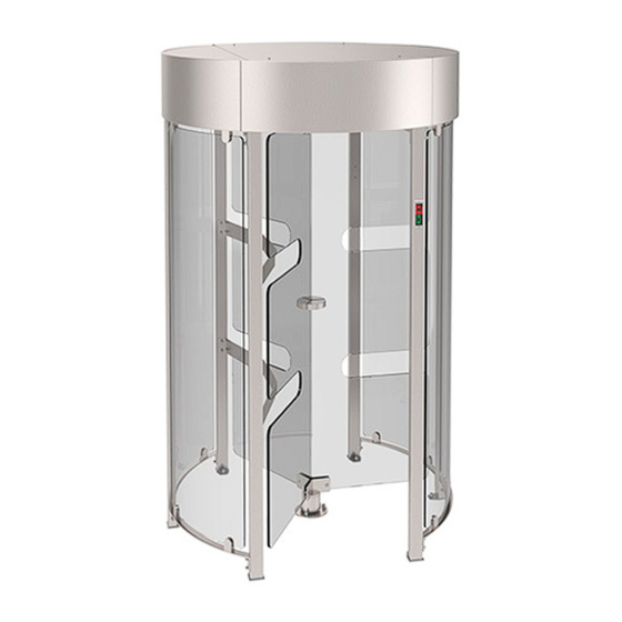
This model works on the principle of a classic full-height turnstile, however side leaves and rotor panels are made of impact-resistant glass. The GlassGO-S full-height turnstile has an elegant look and perfectly fits into interior of the most modern entrances. -
Page 5: Specification
10 000 000 passes - average life of the turnstile till overhaul – not less than 10 years. 1.2. Specification Тable 3 - The key parameters of the turnstile “GlassGO-S” Full-height turnstile Modification of model AUIA.436-05 T1.1.BYС.CC Designation type... -
Page 6: Overall Dimensions
Handle material on rotor panels - AISI 304 / AISI 316 – brushed stainless steel - powder coated RAL Emergency mode in case of power failure: fail-secure (rotor locked in both directions) 1.3. Overall dimensions Fig.2 – Overall dimensions of the turnstile «GlassGO-S»... -
Page 7: Turnstile Design
9 - LED lane light; 10 - RGB indication of pass at bottom doorstep; 11 - Sensors detecting wrong way pass; 12 - Service panel with locks; 13 - Rotor manual release. Fig. 3 – Design of the turnstile «GlassGO-S»... -
Page 8: Turnstile Design
Operation Manual 1.5. Turnstile design 1 – Bottom plate; 2 – Top plate; 3, 4 – Ratchet gears; 5, 6 – Latches; 7, 8 – Springs; 9, 10 – Solenoids; 11 – Closer profile cam; 12 – Closer lever; 13 – Gear motor; 14 –... -
Page 9: Principle Of Turnstile Operation
Operation Manual 1.6. Principle of turnstile operation In the initial state (when solenoids of control mechanism are deenergized) rotor is locked against rotation in both directions. When access enabling command is issued to controller in one of directions: – green arrow is lit on LED display; –... -
Page 10: Layout And Installation
4) The turnstile fixation holes to be marked on the area surface according to the drawings. The turnstile components, placed upright on the installation site, marking can be used as a template. Installation drawing Fig.6 – Installation drawing of Full-Height Turnstile "GlassGo-S"... -
Page 11: Assembly Of Rotors
Operation Manual 2.2. Assembly of rotors: Legend: 1. Hex Socket Head Cap Screws M8x16 (12 pcs); 2. Rotor handle (3 pcs); 3. Bush (12 pcs); 4. Threaded bush (6 pcs); 5. Caprolon washer (12 pcs); 6. Glass rotor leaf (3 pcs) Fig.7 - Assembly and installation of rotor on turnstile support... -
Page 12: Assembly Of Turnstile Parts In The Design Position
(zero rotor position), i.e. corresponded "CLOSED" turnstile mode; From this position it is possible to set the standard operating modes of the turnstile. Fig.8 – General view of installation of the turnstile "GlassGo-S" in the design position... -
Page 13: Installation Of The Turnstile Container
Operation Manual 2.4. Installation of the turnstile container: To access the container, it is necessary: Bottom view of the container a) to open 2 lower service panels of the container “at entrance” and “at exit” Top view of the container b) or remove one top service panel of container by unscrew 4 screws of EN ISO 4762 M4 x16 with a hex key. - Page 14 Operation Manual Container to be fixed to the turnstile enclosure wall and access way wall by means of screws: Legend for container anchors: 1 - Spring washer GOST 6402-70 (8 pcs); 2 - Screw (bolt) ISO 4762 - M8 x 25 (8 pcs); 3 - Flat washer ISO 7089 - 140 HV (8 pcs);...
-
Page 15: General View Of Installed "Glassgo-S
Operation Manual 2.5. General view of installed “GlassGo-S” Fig. 11 - General view of installed “GlassGo-S”... -
Page 16: Turnstile Connection
Operation Manual 3. Turnstile connection Make sure that the installed turnstile is stable and rotor revolving to be checked manually: rotor should revolve smoothly in both directions. Fixation of structure, final installation of smaller components and electrical wiring to be performed according to the wiring diagram (See Annex C);... -
Page 17: Required Inspections
Operation Manual 3.2. Required inspections Then the turnstile is commissioned it is necessary to perform the inspections specified in Table 4. Table 4 LED display Operation Mode Mode Setting at bottom Actions to test performance On display doorstep 1. Turnstile is closed in both Strip is Make sure that rotor can't be... - Page 18 Operation Manual Continued Table 4 FREE button to be pushed for Make sure that rotor can be 8. Free access in Green arrow of turned to 120° repeatedly in access in chosen one direction authorized free access direction ("A" or Strip is free access direction and it and locked...
-
Page 19: Contingency Actions
Operation Manual 3.3. Contingency actions In case of emergency evacuation from rooms and for free personnel exit the turnstile can be unlocked from control panel by sending the relevant command or manually by turning locks with key in the bottom part of container. Two built-in manual release locks (each direction of passage has its own lock) allow, if necessary (e.g. -
Page 20: Description And Operation Of Controller As An Integral Component Of The Turnstile
Operation Manual 4. Description and operation of controller as an integral component of the turnstile 4.1. Turnstile rotor mechanism controller PCB.201.01.00.00 4.1.1 Purpose of the turnstile rotor mechanism controller РСВ.201.01.00.00 The controller is designed for acquisition of commands from the turnstile controller PCB.112.21.20.01 and generation of the motorized mechanism motor control signals. - Page 21 Operation Manual The purpose of controller РСВ.201.01.00.00 (for rotor motorized mechanism) contacts designed for connection of peripherals is shown in Table 6. Table 6 Connector/ Designation Direction Purpose Signal parameters and description contact No X1/1 ENTRY Not applicable X1/2 ENTRY 1) logical «0»...
-
Page 22: Turnstile Controller Рсв.112.21.20.01
Operation Manual 4.2.Turnstile controller РСВ.112.21.20.01 4.2.1. Purpose of controller РСВ.112.21.20.01 The controller РСВ.112.21.20.01 is designed for control of the full-height turnstile operation both under control of authorized access system (hereinafter referred to as AAS) and independently. It provides the required logic of the turnstile operation in various operating modes as well as compliance of control commands from peripherals and generation of report signals. - Page 23 Operation Manual On the board there are 13 jumpers, 40 terminal clamps for connection of wires, 14 of them for external connections, another- for connection to the turnstile units or can be standby. Application of jumpers on the controller board PCB.112.21.20.01: CONTROLLER PCB 112.21.20.01 Table 7 - Application of jumpers...
- Page 24 Operation Manual 4.2.2. Technical features The controller specifications are given in Table 8. Table 8 Parameter name Value of the parameter Number of inputs for receiving control commands Number of signal outputs Type of inputs logic Type of outputs open collector (3 ...
- Page 25 Operation Manual • When rotor rotates to 54º (40º), the output signal “START OF ACCESS "А/В” (“OUT1” or “OUT2”) is removed. Delay of WAITING FOR START OF ACCESS is reset; • When rotor rotates to 64º (48º), ACCESS DETECTION (OUT3 or OUT4) signal is generated. •...
- Page 26 Operation Manual (“OUT7” "PANIC") will be switched to active state during the function action. Barrier rod is lowered after power supply is fed to magnet from output “PSW1” "PANIC". The "PANIC" function is canceled: • After active state is released on input “INP5” "PANIC"); •...
- Page 27 Operation Manual Continued Table 9 1) type of output - open ХТ3/8 INDAR EXIT collector; 2) maximum voltage on ХТ3/9 INDAG EXIT It is used for the turnstile LED the closed key 30 V; display control 3) maximum current of the ХТ3/10 INDBR EXIT...
-
Page 28: Maintenance
Operation Manual 5. MAINTENANCE 5.1. General guidelines The turnstile commissioning and subsequent maintenance to be performed only by the staff to be in charge of the turnstile. The turnstile to be serviced only by the staff having the relevant electrical safety qualification level according to the national requirements. -
Page 29: Current Repair
Operation Manual WARNING: The turnstile not to be washed with water under pressure. There are no user-serviceable parts inside the turnstile. Do not attempt to perform repair such as lubrication, component replacement and adjustment inside the device. All such work to be performed only by qualified technical personnel! 6. -
Page 30: Checking The Product After Repair
Operation Manual Continued Table 12 Check the connectors and wires between controllers (boards) Check and clean fault latches Have no a communication between Adjust or replace the position sensor controllers Turnstile is not Check and clean the locking solenoid The turnstile is not receiving unlocked Check that the access control system is properly an activation signal from the... -
Page 31: Storage And Transportation
Operation Manual 7. STORAGE AND TRANSPORTATION Do not subject the product to sudden shocks or impacts during storage. You need to use transport trolleys to lift or move the product. There should be no corrosive gases and vapors that cause corrosion of the metal in storage rooms, The temperature of the air during storage should not exceed the limits below plus 5 and above plus 40 °C and relative air humidity not more than 80% at a temperature of 20 °C. -
Page 32: Annex А. Overall And Installation Dimensions Of The Full-Height Turnstile "Glassgo-S" Auia.436-02
Annex А. Overall and installation dimensions of the Full-Height Turnstile "GlassGo-S" AUIA.436-05... -
Page 33: Annex B. Control Panel And Connection Diagram
Annex B. Control panel and connection diagram 1 – control panel body; 5 – "FREE ACCESS" mode control button 2 – "SINGLE ACCESS" control button 6 – "PANIC" mode control button mode control button 3 – front plate; 7 – access direction LED display; 4 –... -
Page 34: Annex C. Wiring Diagram Of The Glassgo-S Turnstile
Annex C. Wiring diagram of the GlassGo-S turnstile AUIA 426 PCB 112.21.20.01 AIRLOCK “A” AIRLOCK “B” CONFIG / PSC- CONTROLLER PCB 1.1.1.0 31-1 31-2 31-13 SENSOR SENSOR 32-1 32-13 32-2 Vbat +3.3V +3.3V 33-1 33-13 33-2 PC_13 34-1 34-13 34-2... -
Page 35: Annex D.1. Wiring Diagram Of The Turnstile Connection To Access Control System (Acs) In Pulse Mode
Annex D.1. Wiring diagram of the turnstile connection to access control system (ACS) in pulse mode OPTO XT3.1 XT1.1 RESET OPTO1 Relay 1 Relay 2 XT2.1 Door contact 1 XT .1 Door contact 2 М + GB XT5.1 inp1 - "PANIC" inp2 - "TO BE OPENED A"... -
Page 36: Annex D.2. Wiring Diagram Of The Turnstile Connection To Access Control System (Acs) In Hold Mode
Annex D.2. Wiring diagram of the turnstile connection to access control system (ACS) in hold mode... -
Page 37: Annex D.3. Wiring Diagram Of The Turnstile Connection To Fire Alarm System (Fas)
Annex D.3. Wiring diagram of the turnstile connection to fire alarm system (FAS) OPTO XT3.1 XT1.1 RESET OPTO1 XT2.1 XT .1 М + GB XT5.1 inp1 - "PANIC" inp2 - "TO BE OPENED A" in pulse mode. When command is issued entry is activated for 5 sec. inp3 - "TO BE OPENED B"... -
Page 38: Annex D.4. Wiring Diagram Of The Turnstiles Connection To Fire Alarm System (Fas)
Annex D.4. Wiring diagram of the turnstiles connection to fire alarm system (FAS) OPTO XT3.1 XT1.1 RESET OPTO1 XT2.1 XT .1 М + GB XT5.1 OPTO XT3.1 XT1.1 RESET OPTO1 XT2.1 XT .1 М + GB XT5.1... -
Page 39: Annex D.5. Wiring Diagram Of The Turnstile Connection To Control Panel
Annex D.5. Wiring diagram of the turnstile connection to control panel OPTO XT1.1 XT3.1 RESET OPTO1 XT2.1 XT .1 М + GB XT5.1... - Page 40 Manufacturer: LLC TiSO-PRODUCTION 14, Promyslova Street, Kyiv, 02088, Ukraine Phone: +38 (044) 291-21-11 Tel./fax: +38 (044) 291-21-02 E-mail: sales@tiso.global www.tiso.global SERVICE CENTER e-mail: service1@tiso.global Our equipment meets the requirements of European standards: EN ISO 12100:2010, EN ISO 14118:2018, EN 60204-1:2018, EN ISO 13857:2019, EN 61000-6-1:2007, EN 61000-6-3:2007/A1:2011/AC:2012 and meets the requirements of the following EU Directives: 2014/30/EU;...
Need help?
Do you have a question about the GLASSGO-S and is the answer not in the manual?
Questions and answers