
Related Manuals for Tiso SpeedBlade T3.KCD.XV.X Series


Summary of Contents for Tiso SpeedBlade T3.KCD.XV.X Series
- Page 1 «TiSO-PRODUCTION» LTD WAIST-HIGH TURNSTILE «SpeedBlade» Т3.КСD.ХV.X OPERATION MANUAL AUIA177 OM 2018...
-
Page 2: Table Of Contents
CONTENTS INTRODUCTION ..........................3 1. DESCRIPTION AND OPERATION....................5 1.1 General Information and Designation ..................5 1.2 Specifications........................... 6 1.3 Configuration and Scope of Delivery ..................7 1.4 Design and operation ......................10 1.5 Instrumentation, tools and accessories .................. 12 1.6 Description and operation of controllers as integral component of the turnstile.... -
Page 3: Introduction
INTRODUCTION This Operation Manual (hereinafter referred to as OM) covers the servo-operated waist-high turnstile of “SpeedBlade" type (hereinafter referred to as the "turnstile"). The Operation Manual contains information about design, specifications, installation for proper operation and maintenance of the turnstile. This Operation Manual is prepared in compliance with the specification requirements ТU U 31.6-32421280-004:2010. - Page 4 WARNINGS TO THE CUSTOMER ON SAFE OPERATION OF THE TURNSTILE These warnings are designed for ensuring of safety during operation of the turnstile to prevent violation of safety characteristics by improper installation or operation. These warnings are aimed at drawing attention of the customer to safety problems. GENERAL WARNINGS The Operation Manual is an integral part of the product and it should be handed over to the customer.
-
Page 5: Description And Operation
1. DESCRIPTION AND OPERATION 1.1 General Information and Designation 1.1.1 Purpose : The motorized turnstile is designed for pedestrian movement control at access points of industrial enterprises, banks, stadiums, administrative facilities etc. by access control system (from magnetic card readers) or manually (from manual control panel). Traffic flow capacity of the turnstile with personal identification is at least 30 persons per minute in one direction 1.1.2 Dimensions and weight of the turnstile correspond to the values specified in Table 1. -
Page 6: Specifications
Table 3 For climatic Parameter value Operation conditions modification Ambient temperature + 1 to + 40 °С Relative humidity 80 % at 20 ºС Ambient temperature allowable 84 to 106,7kPa pressure Transportation temperature range - 40 to + 50 °С Storage temperature range - 5 to + 40 °С... -
Page 7: Configuration And Scope Of Delivery
1.3 Configuration and Scope of Delivery 1.3.1 The turnstile design depends on the number of access ways: 1) For arrangement of single access way the turnstile is a set of left-hand and right-hand pedestals, each of which has one glass blade (reference designation Т3.КСD.ХV.1); 2) For arrangement of two or more access ways the turnstile is a set of two single blade pedestals and one or more additional pedestal with two blades (reference designation Т3.КСD.ХV.Х). - Page 8 – controllers; – seven access sensors; – proximity identification card reader*; – power supply unit. Optionally the pedestal can be completed with battery*. For the single turnstile a control panel with power supply unit, automatic circuit-breaker and battery is installed only inside the pedestal Master on the protected area side.
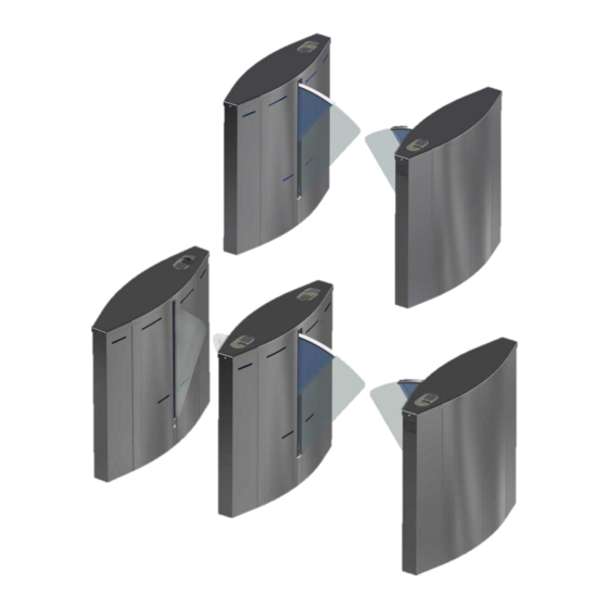
- Page 9 1 – location of identification card readers and LED display; 2 – side LED display; 3 – access sensor; 4 – telescopic glass blade ; 5 – turnstile base; 6 – lid; 7 – actuator; 8 – turnstile body; 9 - glass blade; Fig.
-
Page 10: Design And Operation
1.4 Design and operation General appearance 1.4.1 1 – устройство считывания идентификационных карт и световое табло индикации; 2 – световое табло индикации; 3 – датчики прохода; 4 – телескопическая стеклянная створка; 5 – основание турникета; 6 – крышка; 7 – привод; 8,9 –... - Page 11 1.4.2.2 The turnstile’s status (Fig. 5) is displayed by the LEDs 1,2, installed on the pedestal frame elements. Constantly lit blue LED means the turnstile initial state. In case of attempt of unauthorized access red LED starts blinking and sound signal is generated. When opening command is received, signal is transformed to green arrow from the side of authorized access.
-
Page 12: Instrumentation, Tools And Accessories
1.5 Instrumentation, tools and accessories Dedicated tools are not required for the turnstile installation (multi-purpose measurement instrumentation and installation tools are sufficient). 1.6 Description and operation of controllers as integral component of the turnstile 1.6.1 Controller AUIA.206.21.20.00 1.6.1.1 Appearance of controller AUIA.206.21.20.00 is shown in Figure 6. 1.6.1.2 Description of operation The controller provides algorithm of operation of the whole turnstile. - Page 13 (outputs "OUT1" or/and "OUT2") and starts tracing position and direction of pedestrian movement in the turnstile access way, analyzing 6 IR barriers. As soon as pedestrian is behind the blades line they close, the controller generates the signal "DETECTION OF ACCESS" of 0,3 second duration (outputs "OUT3"...
- Page 14 "LOCK OF ACCESS" The turnstile switches to this mode only upon command "LOCK OF ACCESS А/В" arrived via interface RS-485 from control panel. Thus red LED is blinking from the side of locked access, glass blades are closed (if the turnstile is not open for free or single access from opposite side), controller does not respond to signals of inputs "INP1"...
- Page 15 Continued Table 5 OUT3 signal (Factory ХТ3/4 («DETECTION OF EXIT setting) – logical «0» Signal appears during ACCESS А») (connection on GND) barring of the second last OUT4 IR barrier and continues ХТ3/5 («DETECTION OF EXIT 0,2 sec. ACCESS В») Output is active in case ХТ3/6 OUT5 («ALARM»)
- Page 16 Fig. 7 – Appearance of controller РСВ.201.01.00.00 1.6.2.2 Description of operation The controller is designed to control DC motor, intended to move the turnstile blades, and electromagnetic brake installed on motor shaft. Control is performed based on the signals coming from magnetic sensor as well as from motor current sensor.
- Page 17 Continued Table 6 X1/9 “-“ power supply X1/10 (common wire) X1/11 X1/12 +5 V EXIT Not applicable X2/1 GRN1 EXIT Not applicable X2/2 RED1 EXIT Not applicable X2/3 GRN2 EXIT Not applicable X2/4 RED2 EXIT Not applicable X2/5 -MG1 EXIT Not applicable 1) type of output –...
-
Page 18: Intended Use
2 INTENDED USE 2.1 Operation restrictions 2.1.1The turnstile must be used in the environment specified in p. 1.1.4 of this document subject to the specifications listed in section 1.2. IT IS FORBIDDEN: TO MISUSE THE TURNSTILE (See Section 1 "DESCRIPTION OPERATION");... - Page 19 Cables to be laid in compliance with electric code; The turnstile to be installed by at least 2 installers. 2.2.4 Tools and accessories to be used (Fig.8): puncher; concrete drills (according to diameter of anchors included in the turnstile scope of delivery);...
- Page 20 General layout of the “SpeedBlade” turnstile access ways 2.2.5 Fig. 9 – “SpeedBlade” type turnstile layout options 2.2.6 Installation procedure. The turnstile installation procedure is as follows: 1) The package integrity to be checked prior to unpacking. If package is damaged, then damages to be fixed (picture to be taken, damage report to be made);...
- Page 21 Two frame screws to be loosened and removed at the bottom of the turnstile frame base (View С); The turnstile to be removed from pallet; Fig. 10 – Turnstile removal from pallet 4) Make sure that the turnstile installation area is ready as follows: ...
- Page 22 IMPORTANT! Pedestals are linked by control line optical sensor system requiring accurate positioning of pedestals. The relative position of pedestals and vertical position of the turnstile to be respected. Fig. 11– Installation dimensions of “SpeedBlade” type turnstile The relevant holes to be drilled on the surface according to the marking due to diameter of anchors (12×120М10) for the turnstile fixation.
- Page 23 † Fig. 12 – Cable entries between the turnstile † Master («SpeedBlade»-1 )– pedestal Slave («SpeedBlade» -1)- pedestal Master/Slave («SpeedBlade» -2 ) – double blade pedestal...
- Page 24 Fig.13 – Cable entries Master and Slave pedestals 9) The length of cable free ends to be at least 1 m to provide cable entry, termination and connection to the relevant terminals in the turnstile post. 10) The cable outlet point to be aligned with the hole on the turnstile mounting plate.
- Page 25 - G (GND) – common wire of control panel; - A (RSA) – RSA wire of control panel link; - B (RSB) – RSB wire of control panel link; c) The turnstile to be earthed, power supply cable to be connected the turnstile according to wiring diagrams (See Annex B).
-
Page 26: Preparation For Use
Fig. 18 - Installation of card reader 2.3 Preparation for use 2.3.1 Commission guidelines Prior to the turnstile energization: make sure of proper connection and good condition of all connecting cables; clear the turnstile blade opening area from foreign particles. When mains cable of power supply unit is connected to the network, the turnstile actuating mechanism is energized. -
Page 27: Contingency Actions
Continued Table 7 Green arrow of authorized free "FREE" button to be pushed for access in chosen direction is lit 4. Free access in access in chosen direction(“A” or and blue LED display in opposite one direction “B”) direction is lit Both "FREE"... -
Page 28: Maintenance
In case of the mains power failure the turnstile automatically switches to power from the backup battery (optional). If the mains power is not recovered and battery is discharged, the glass blades are fully put manually to the turnstile pedestal slots to make access way free. 3 MAINTENANCE 3.1 General guidelines 3.1.1 Commissioning and subsequent maintenance of the turnstile to be performed only by... -
Page 29: Routine Maintenance
Table 8 Detergent description Manufacturer Country of origin Stainless steel cleaning spray “Stainless Group of European Steel Cleaner And Polish” companies Cleaning fluid “Well Done” Well Done Hungary Stainless steel products and other metals XANTO United Kingdom cleaner “XANTO STEEL 3in1” «Dr.BECKMANN»... -
Page 30: Speedblade" Turnstile Blade Initialization Procedure
Continued Table 8 to be checked. Availability of Turnstile does not obtain actuation signal from ACS to be actuation signal from ACS. checked. Magnetic sensor to be Magnetic sensor to be adjusted or Blade knocks checked. PCB to be replaced. Control panel sends Wires to be checked. - Page 31 7) Presence signals rotation anglechanging, speed and zero position on controller PCB 201 - terminals: IN5, IN6, IN7, IN8. During blade opening and closing: - IN5, IN6 – should exchange winks. - IN7 – is lit brightly if the blade is not moved or is moved slowly.
-
Page 32: Postrepair Checkout
4.3 Postrepair checkout The turnstile performance is checked after repair according to p. 2.3.2 of this OM. 5 TRANSPORTATION AND STORAGE 5.1 Turnstile storage It is forbidden to subject the turnstile to jerks and impacts during storage. Transportation trolleys to be used for handling of the turnstile. In storage facilities there should not be aggressive gases and vapours causing metal corrosion. -
Page 33: Manufacturer'swarranty And Terms Of Warranty Meaintenance
MANUFACTURER'S WARRANTY TERMS WARRANTY MEAINTENANCE 7.1. The manufacturer guarantees good state and declared quality of the turnstile if conditions of transportation, storage, installation and operation are observed by the consumer 7.2. The warranty period of the turnstile from the date of sale is 12 months unless otherwise specified by agreement. - Page 34 Manufacturer: "TiSO-PRODUCTION" LTD 72 Yamskaya str., 03150 Kiev, Ukraine Tel.: +38 (044) 291-21-11 Tel../Fax: +38 (044) 291-21-02 E-mail: sales@tiso.global www.tiso.global Our equipment complies with requirements of the European Standards: EN 60335-1:2002, EN 61000-6-1:2007; EN 61000-6-3:2007; EN 61000-4-2:2009; EN 61000-4-3:2006; EN 61000-4-4:2004; EN 61000-4-5:2006; EN 61000-4-11:2004 and is in conformity with requirements of the following EC Directives: 2004/108/EC;...
-
Page 35: Annex А Overall And Installation Dimensions Of The "Speedblade" Type Turnstile T3.Kcd.xv.1
Annex А (mandatory) Overall and installation dimensions of the “SpeedBlade” type turnstile T3.KCD.XV.1 Fig.А.1 – Single turnstile (right-hand and left-hand pedestal (Master and Slave)) - Page 36 Continued Annex А Overall and installation dimensions of the “SpeedBlade” type turnstile T3.KCD.XV.2 Fig.А.2 – Double turnstile (right-hand, right-hand/left-hand and left-hand pedestal (Master, Master / Slave and Slave))
-
Page 37: Annex B Control Panel And Connection Diagram
Annex B (mandatory) Control panel and connection diagram 1 – control panel body; 5 – "FREE ACCESS" mode control button 2 – "SINGLE ACCESS" mode control 6 – "PANIC" mode control button button 3 – front plate; 7 – access direction LED display; 4 –... - Page 38 Continued Annex B Control panel and connection diagram Fig. B.2 – Connection diagram of control panel AUIA.114.02.00.00...
-
Page 39: Annex C.1 Wiring Diagram Of The "Speedblade" Type Turnstile
Annex C.1 (mandatory) Wiring diagram of the "SpeedBlade" type turnstile ВЕДУЩАЯ СТ ОЙКА КОН ТРО ЛЛЕР Конт роллер АЮИА. 206.21 . 2 0.00 PCB.20 5.01.05.00 PCB201.01.0 0.00 XS3 1 XP1 PCB 7 3 0 .0 1 10- 2 +12V +1 2 V +12V IR IN1 SPEED... -
Page 40: Annex D.1 Diagram Of The Turnstile Connection To Access Control System (Acs)
Annex D.1 (mandatory) Diagram of the turnstile connection to access control system (ACS) inp1- " TO BE OPENED A" in pulse mode. When command is issued the input is activated for 5 sec. inp2- " TO BE OPENED B" in pulse mode. When command is issued the input is activated for 5 seconds. -
Page 41: Annex D.2 Diagram Of The Turnstile Connection To Access Control System (Acs)
Annex D.2 (mandatory) Diagram of the turnstile connection to access control system (ACS) inp1- " TO BE OPENED A" in pulse mode. When command is issued the input is activated for 5 sec. inp2- " TO BE OPENED B" in pulse mode. When command is issued the input is activated for 5 seconds. -
Page 42: Annex D.3 Diagram Of The Turnstile Connection To Fire Alarm (Fa)
Annex D.3 (mandatory) Diagram of the turnstile connection to fire alarm (FA) inp1- " TO BE OPENED A" in pulse mode. When command is issued the input is activated for 5 sec. inp2- " TO BE OPENED B" in pulse mode. When command is issued the input is activated for 5 seconds. -
Page 43: Annex D.4 Diagram Of The Turnstile Connection To Control Panel
Annex D.4 (mandatory) Diagram of the turnstile connection to control panel 5 4 3 2 1...
Need help?
Do you have a question about the SpeedBlade T3.KCD.XV.X Series and is the answer not in the manual?
Questions and answers