
Related Manuals for Tiso Speed Gate Series


Summary of Contents for Tiso Speed Gate Series
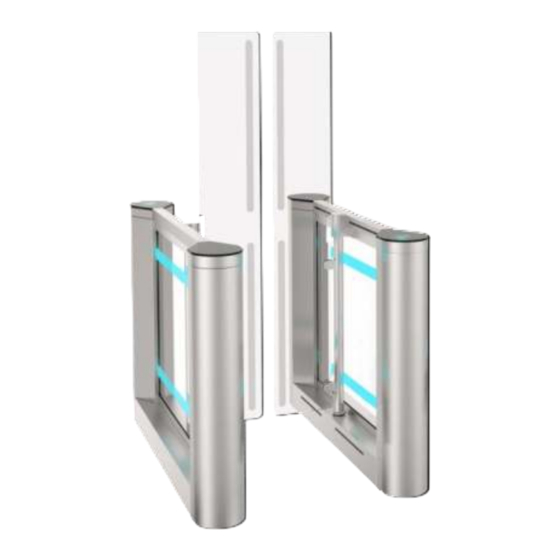
- Page 1 "TiSO-PRODUCTION" LTD WAIST-HIGH TURNSTILES Speed Gate series SWEEPER-HG-BM(550 - 900) SWEEPER-HGW-BM(1200) OPERATION AND INSTALLATION MANUAL 2023 AUIA.207-03, AUIA.207-04 rev.1.3 (combined) UKRAINE...
-
Page 2: Table Of Contents
CONTENTS INTRODUCTION ................................3 WARNINGS TO THE CUSTOMER ON SAFE OPERATION OF THE TURNSTILE ..........4 1. DESCRIPTION AND OPERATION ........................... 5 1.1 General Information and Purpose ........................5 1.2 Specifications ..............................7 1.3 Configuration and Scope of Delivery......................... 7 1.4 Design and operation ............................ -
Page 3: Introduction
INTRODUCTION This Operation Manual (hereinafter referred to as OM) covers the "SWEEPER-HG-BM" and "SWEEPER-HGW- BM" type waist-high turnstile (hereinafter referred to as the "turnstile"). The Operation Manual contains information about design, specifications, installation for proper operation and maintenance of the turnstile. This Operation Manual is prepared in compliance with the specification requirements ТU U 28.9- 32421280- 005:2018. -
Page 4: Warnings To The Customer On Safe Operation Of The Turnstile
WARNINGS TO THE CUSTOMER ON SAFE OPERATION OF THE TURNSTILE These warnings are designed for ensuring of safety during operation of the turnstile to prevent violation of safety characteristics by improper installation or operation. These warnings are aimed at drawing attention of the customer to safety problems. -
Page 5: Description And Operation
1. DESCRIPTION AND OPERATION 1.1 General Information and Purpose 1.1.1 Purpose: The motorized turnstile is designed for pedestrian movement control at access points of industrial enterprises, banks, stadiums, administrative facilities etc. controlled by access control system (from proximity card readers) or manually (from manual control panel). - Page 6 Table 2 Dimensions, mm Designation of Max. weight, kg Width of lane Width of set for modification type Height (H) Length (L) one lane (W) 165* Sweeper-HGW-BM 1500/1800 1750 1282 170* 1200 1582 180* * When the turnstile with more than two lanes is ordered: W= 1392 ·...
-
Page 7: Specifications
1.1.4 The operation condition parameters according to GOST 15150-69 are specified in Table 4 for climatic modification NF4 Table 4 Parameter value for climatic modification NF4 Operation conditions Ambient air temperature +1°С to +40°С 80% at +20ºС Relative air humidity (non-condensign) Ambient air allowable pressure 84 to 106,7 kPa... - Page 8 swing-type side pieces with locks; top, side and bottom linings; decorative lid; glass partition; swing glass leaf; LED display (top and side). Inside the cabinet there are installed: – BMDrive® servo-drive; – Ten access sensors. The cabinet design provides a space for installation of proximity identification card reader.
-
Page 9: Design And Operation
1.4 Design and operation 1.4.1 Turnstile design (See Fig. 3-4) The body of the turnstile cabinet is a frame on which are mounted stainless steel side lining 7, bottom lining 8, sensor lid 6, lid of top frame 14 and 8mm-tempered glass partition 9. A card reader lid 5 is fixed on frame top (lining material is specified by the order). - Page 10 General appearance of the turnstile operating mechanism and control desk 1.4.2 The cabinet operating mechanism and control desk is shown in Figure 4. 1 – motor magnet sensor; 2 – booster converter PCB.203.001; 3 – glassholder shaft; 4 – electromagnetic tooth clutch;...
- Page 11 1.4.3 Principle of operation 1) Turnstile status indication Fig.5 – Light indication of the turnstile status Standby mode 2) Access cycle: 1. In the initial state the turnstile glass leaves are located perpendicular to the body blocking the access. 2. The turnstile is opened for access in the direction "А" or "В" after the appropriate command from ACS or control panel is issued.
-
Page 12: Description And Operation Of Controllers As An Integral Component Of The Turnstile
1.5 Description and operation of controllers as an integral component of the turnstile 1.5.1 Main controller АUIA.206.21.20.00 1.5.1.1 Controller AUIA.206.21.20.00 is shown in Figure 7. 1.5.1.2 Description of operation The controller provides algorithm of operation of the whole turnstile. It is assembled on the card from foil-clad textile laminate of 120 х... - Page 13 1 - ON - when command is generated the turnstile will be opened for 5 seconds; OFF - when command is generated the turnstile will be opened for the time set by ACS; 2 - ON- the state of outputs OUT1-5 will be NC; - OFF - the state of outputs OUT1-5 will be NO;...
- Page 14 Table 7 Connector/ Signal parameters and Designation Direction Purpose Contact No description 1) logical «0» (0 2,2) V; INP1 ХТ4/1 ENTRY "TO BE OPENED FOR 2) logical «1» (3 5) V; ("TO BE OPENED A") SINGLE/FREE ACCESS" INP2 3) active level of signal ХТ4/2 ENTRY...
-
Page 15: Motor Controller Аuia.401.00.00-01
1.5.2 Motor controller АUIA.401.00.00-01 1.5.2.1. Description of motor controller АUIA.401.00.00-01 The controller АUIA.401.00.00-01 is designed to control BMDrive gear motors, which drives the turnstile ® leaves in motion. At each passage of turnstile installed pair of controllers АUIA.401.00.00-01: the first controller drive the leaf in the Master cabinet, the second controller drive leaf in the Slave cabinet. - Page 16 1.5.2.2. Description of the main page of the controller An OLED display and 4 control buttons are installed on the front side of the AUIA.401.00.00-01 controller for the displaying the current state of the controller and for configuration settings at menu After initialization of the controller the main page of the menu is displayed on the screen.
- Page 17 № Direction Designation Description Connector/contact XT1/1 EXIT Common wire of the control panel (GND ) XT1/2 DATA RS485 (1) communication line with 7-button TISO control panel XT1/3 DATA XT1/4 EXIT Power output for control panel (+12V) XT1/5 +12V EXIT Power output (+12V) for additional devices...
- Page 18 Continuation of table 8 XP6/4 +12V EXIT Power supply of leaf position sensor XP8/1 ENTRY Jumper of line RS 485 (2) pull up resistor XP8/2 ENTRY Jumper of line RS 485 (2) termination resistor (load) XP8/3 ENTRY Jumper of line RS 485 (2) pull up resistor Сommon XP2/1 EXIT...
-
Page 19: Intended Use
2 INTENDED USE 2.1 Operation limitations 2.1.1 The turnstile must be used in the environment specified in p. 1.1.4 of this document subject to the specifications listed in section 1.2. It Is Forbidden: 1) to misuse the turnstile (see section 1 "description and operation"); 2) to use the turnstile unearthed;... - Page 20 2.2.5 SWEEPER-HG-BM type turnstile layout options Fig. 13 – SWEEPER-HG-BM and SWEEPER-HGW-BM type turnstile layout options WARNING: The damages occurred during the turnstile transportation are not covered by the manufacturer's warranty liabilities. 2.2.6 Installation procedure The turnstile installation procedure is as follows: 1) The package integrity to be checked prior to unpacking.
- Page 21 IMPORTANT! Cabinets are linked by control line optical sensor system requiring accurate positioning of cabinets. The relative position of cabinets and vertical position of the turnstile to be respected. Fig.15– Installation dimensions of SWEEPER-HG-BM...
- Page 22 Fig.16– Installation dimensions of SWEEPER-HGW-BM WARNING: The turnstile installation and fixation to be performed only after all electric cables are pulled. 8) The following cables to be run to the turnstile installation site: Power supply cable 230 V ~; ...
- Page 23 Fig.17 – General view of connection between cabinets...
- Page 24 Option 1 Option 2 Fig.18 – Options of cable connection between cabinets Master and Slave 9) The length of cable free ends to be at least 1 m to provide their entry, termination and connection to the relevant terminals in the turnstile rack. 10) The cable outlet point to be aligned with the hole on the turnstile frame mounting plate.
- Page 25 11) To access the fixation holes and terminal blocks it is required to do the following on both sides of cabinet: 1. - Locks to be unlocked by key and door to be turned (See Fig. 19); 2. - Bottom linings to be removed unscrewing screws;...
-
Page 26: Preparation For Use
13) Installation of proximity card reader (supplied by order for a fee) , upon availability of access control system (ACS) (Fig.22). - The turnstile lid b (or glass top) to be removed by unscrewing screws а from frame; - Screws to be unscrewed and acrylite to be removed;... -
Page 27: Contingency Actions
Continuation of table 9 Both "FREE" buttons to be Swing leaves are 5. Free access in both Green arrows of authorized free rotated at 90° in the pushed for access in both directions access in both directions are lit directions («A» and «B») intended direction Swing leaves are rotated at 90°... -
Page 28: Maintenance
3 MAINTENANCE 3.1 General guidelines 3.1.1 Commissioning and subsequent maintenance of the turnstile to be performed only by the staff to be in charge of the turnstile.. 3.1.2 The turnstile to be serviced only by the staff having the relevant electrical safety qualification level according to the national requirements.. -
Page 29: Routine Maintenance
4 ROUTINE MAINTENANCE 4.1 General guidelines Minor malfunctions of the turnstile are listed in Table 11 and are remedied by the customer. More complicated malfunctions are remedied by the manufacturer’s representative. IMPORTANT: INSPECTION, CLEANING, REPAIR OF THE TURNSTILE COMPONENTS TO BE PERFORMED ONLY AFTER THE TURNSTILE DEENERGIZATION ! 4.2 Possible malfunctions Possible malfunctions of the turnstile and their remedies are listed in Table 11. -
Page 30: Adjustment Of The Zero Position Of Leaf For "Sweeper- Hg-Bm" ("Sweeper- Hgw-Bm")
Continuation of table 11 Leaf opening manually to be checked with Mechanism jamming turned off power supply. “FREE ACCESS” mode is set. Mechanism components to be checked Infrared sensors are out of order. "Free access" mode to be turned off ... -
Page 31: Transportation And Storage
Option ІІ (with АUIA.401.00.00-01) Run the menu holding for 2 seconds the lower button (1) on the controller АUIA.401.00.00- choose “Calibration”- >”GateZeroSet” controller. If you request a calibration procedure, the turnstile will go to “OFF” mode. Set the zero point of both leaves of Master and Slave cabinets manually (CLOSE position (3)) ... -
Page 32: Annex А1. Design And Dimensions Of The "Sweeper-Hg-Bm" Type Turnstile
Annex А1. Design and dimensions of the "SWEEPER-HG-BM" type turnstile... -
Page 33: Annex А2. Design And Dimensions Of The "Sweeper-Hg-Bm-1" And "Sweeper-Hg-Bm-2" Type Turnstile
Annex А2. Design and dimensions of the "Sweeper-HG-BM-1" and "Sweeper-HG-BM-2" type turnstile... -
Page 34: Annex А3. Design And Dimensions Of The "Sweeper-Hgw-Bm" Type Turnstile
Annex А3. Design and dimensions of the "SWEEPER-HGW-BM" type turnstile... -
Page 35: Annex B. Control Panel And Connection Diagram
Annex B. Control panel and connection diagram 1 – control panel housing ; 5 – "FREE ACCESS" mode control button; 2 – "SINGLE ACCESS" mode control button 6 – "PANIC" mode control button; 3 – front plate; 7 – access direction LED display; 4 –... -
Page 36: Continued Annex B. Control Panel And Connection Diagram
Continued Annex B. Control panel and connection diagram Figure B.2 – Connection diagram of control panel AUIA.114.02.00.00... -
Page 37: Annex C.1. Wiring Diagram Of The Sweeper-Hg-Bm 1.1 (Sweeper-Hgw-Bm 1.1) Master Auia.207-03 (Auia.207-04) Rev 0.7 Type Turnstile
Annex C.1. Wiring diagram of the SWEEPER-HG-BM 1.1 (SWEEPER-HGW-BM 1.1) Master AUIA.207-03 (AUIA.207-04) Rev 0.7 type turnstile MINI-FIT 8 Z5BLD120-24GUL ПВ3 0 .7 5 (Gre e n ) MOT B (V) Hall C (W) ПВ3 0 .7 5 (Ye l l o w ) MOT A (U) ПВ3 0 .7 5 (Bl u e ) MOT C (W) -
Page 38: Annex C.2 Wiring Diagram Of The "Sweeper-Hg-Bm" ("Sweeper-Hgw-Bm") Type Turnstile Bm 1.2 Slave
Annex C.2 Wiring diagram of the "SWEEPER-HG-BM" ("SWEEPER-HGW-BM") type turnstile BM 1.2 Slave AUIA.207-03 (AUIA.207-04) Rev 0.7 A A1 P CB .205.01.05.00 X S 25 X P 1 +12V M INI-FIT 8 Z5BLD120-24GUL ПВ3 0 .7 5 (G re e n ) P CB 715.001 1 0 0 MOT B (V) -
Page 39: Annex C.3. Wiring Diagram Of The Sweeper-Hg-Bm 2 (Sweeper-Hgw-Bm 2) Master/Slave Auia.207-03 (Auia.207-04) Rev 0.7 Type Turnstile
Annex C.3. Wiring diagram of the SWEEPER-HG-BM 2 (SWEEPER-HGW-BM 2) Master/Slave AUIA.207-03 (AUIA.207-04) Rev 0.7 type turnstile AA 1 M I N I - FI T 8 Z5 BL D1 2 0 -2 4 GUL П В3 0. 75 ( G r een) M OT B (V) BL 1 BL 2... -
Page 40: Annex D.1.Diagram Of The Turnstile Connection To Access Control System (Acs)
Annex D.1.Diagram of the turnstile connection to access control system (ACS) Relay 1 Relay 2 Door contact 1 Door contact 2 inp1 - "TO BE OPENED A" in pulse mode. When command is issued entry is activated for 5 sec. inp2- "TO BE OPENED B"... -
Page 41: Annex D.2. Diagram Of The Turnstile Connection To Access Control System (Acs)
Annex D.2. Diagram of the turnstile connection to access control system (ACS) inp1- " TO BE OPENED A" in pulse mode. When command is issued the input is activated for 5 sec. . inp - 2 " TO BE OPENED B" in pulse mode. When command is issued the input is activated for 5 seconds. -
Page 42: Annex D.3. Diagram Of The Turnstile Connection To Fire Alarm (Fa)
Annex D.3. Diagram of the turnstile connection to fire alarm (FA) inp1- " TO BE OPENED A" in pulse mode. When command is issued the input is activated for 5 sec. inp - 2 " TO BE OPENED B" in pulse mode. When command is issued the input is activated for 5 seconds. -
Page 43: Annex D.4.Diagram Of The Turnstile Connection To Control Panel
Annex D.4.Diagram of the turnstile connection to control panel 5 4 3 2 1... -
Page 44: Service Center
Manufacturer: LLC TiSO-PRODUCTION 14, Promyslova Street, Kyiv, 02088, Ukraine Phone: +38 (044) 291-21-11 Tel./fax: +38 (044) 291-21-02 E-mail: sales@tiso.global www.tiso.global SERVICE CENTER e-mail: service1@tiso.global Our equipment meets the requirements of European standards: EN ISO 12100: 2010; EN 614-1: 2006 + A1: 2009; EN 1037: 1995 + A1: 2008; EN 60204-1: 2006; EN 953: 1997 + A1: 2009;...
Need help?
Do you have a question about the Speed Gate Series and is the answer not in the manual?
Questions and answers