
Related Manuals for Tiso GATE-STE AUIA.203-05 Series


Summary of Contents for Tiso GATE-STE AUIA.203-05 Series
- Page 1 “TiSO-PRODUCTION” LTD WAIST-HIGH TURNSTILE ELECTROMECHANICAL SWING GATE “GATE-STE” OPERATION MANUAL AUIA 203-05 OM (rev.1.1) UKRAINE 2023...
-
Page 2: Table Of Contents
Operation Manual 2 CONTENTS INTRODUCTION ........................... 3 WARNINGS TO THE CUSTOMER ....................4 ON SAFE OPERATION OF THE TURNSTILE ................4 1 DESCRIPTION AND OPERATION ................... 4 1.1 General Information and Purpose ....................4 1.2 Specification ..........................6 1.3 Configuration and Scope of Delivery ..................6 1.4 Design and operation ......................... -
Page 3: Introduction
Operation Manual 3 INTRODUCTION This Operation Manual (hereinafter referred to as OM) covers nonservo waist-high turnstile of swing gate type with electromagnetic lock (hereinafter referred to as the " turnstile "). The Operation Manual contains information about design, specifications, installation for proper operation and maintenance of the turnstile. -
Page 4: Warnings To The Customer
Operation Manual 4 WARNINGS TO THE CUSTOMER ON SAFE OPERATION OF THE TURNSTILE These warnings are designed for ensuring of safety during operation of the turnstile to prevent violation of safety characteristics by improper installation or operation. These warnings are aimed at drawing attention of the customer to safety problems. GENERAL WARNINGS Safety measures and requirements specified in this in this OM must be observed: –turnstile must be connected to ground loop prior to operation;... - Page 5 Operation Manual 5 Table 1 - The gate dimensions Model of the gate AUIA.203-05 “Gate-STE” Designation of gate type depending on the direction of leaf rotation: - clockwise T3.КВН.SL T3.КВН.PL T3.КВН.KL - counterclockwise T3.КВН.SP T3.КВН.PP T3.КВН.KP Angle of leaf rotation 90°...
-
Page 6: Specification
Operation Manual 6 Continued table 2 Altitude above sea level up to 2000m explosion-proof, does not contain current-conducting dust, aggressive gases and vapors in concentration destroying Environment isolation and metals, disturbing normal operation of the equipment installed in turnstiles in enclosed spaces in the absence of direct impact of Installation site precipitations and solar radiation vertical, deviation from vertical position no more than 1º... -
Page 7: Design And Operation
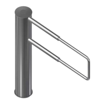
Operation Manual 7 Legend: 1 - Base with frame assembly; 2 - Housing; 3 - Lid; 4 –Telescopic stainless steel leaf; 5 - Mechanism of gate rotation; 6 - Control unit; 7 - Screws for adjusting the passage width; Fig. 2 – Design of Swing gate “Gate-STE” 1.3.2 Turnstile Scope of Delivery The turnstile is delivered by one package. - Page 8 Operation Manual 8 Control unit 6 is intended for power supply and control of turnstile. 1.4.1.5 The control panel is a small desktop device Upper support with in plastic case and is designed for setting and indication electromagnetic of operating modes when the turnstile is operated clutch manually.
-
Page 9: Instrumentation, Tools And Accessories
Operation Manual 9 Table 4- Turnstile operating modes Operation Value of signal IN1- Principle modes Locking of A tubular leaf is blocked from 90 ° rotation in both no enable signal access directions. “Push and go” principle: you should manually turn the gate tubular leaf by 90 °... -
Page 10: Description And Operation Of Controllers As A Component Of The Turnstile
Operation Manual 10 1.6 Description and operation of controllers as a component of the turnstile 1.6.1 Description and operation of the turnstile controller РСВ.705.002 The controller is designed for acquisition of commands from external control devices (control panel, access control system etc.) and generation of control signals for swing gate mechanism. - Page 11 Operation Manual 11 1.6.2. Description of jumper configuration J1-J6 The position of the turnstile-gate leaf is fixed by an induction position sensor. If the sensor output is active the leaf closed; If the sensor output isn’t active the leaf opened;...
-
Page 12: Intended Use
Operation Manual 12 2 INTENDED USE 2.1 Operation restrictions 2.1.1 The turnstile must be used in the environment specified in p. 1.1.5 of this document subject to the specifications listed in section 1.2. IT IS FORBIDDEN: 1) TO MISUSE THE TURNSTILE (See section 1 "DESCRIPTION AND OPERATION");... - Page 13 Operation Manual 13 2) The turnstile to be unpacked and inspected for defects and damages as well as completeness to be checked according to the turnstile technical passport. WARNING: When the turnstile damages are detected or in case of shortage of delivery, installation work to be stopped and the turnstile supplier to be referred to.
- Page 14 Operation Manual 14 Install protective housing of the control unit (10) on the frame (1) of the turnstile assembly; - The housing (2) of the gate shall be connected to the tubular leaf (4) by two screws (12) - M16x22, tightening them from inside of gate housing (2);...
- Page 15 Operation Manual 15 11) Turnstile connection: а) Power supply cable ~220 V to be connected. - Phase (L) to be connected to the circuit breaker; - Neutral (N) to be connected to terminal Gate mechanism ~220V (N); controller - Earth (РЕ) to be connected to earthing terminal (РЕ).
-
Page 16: Preparation For Use
Operation Manual 16 2.3 Preparation for use 2.3.1 Commission guidelines Prior to the turnstile energization 1) make sure of proper connection and good condition of all connecting cables; 2) clear the turnstile’s leaf rotation area from foreign particles. Rotation of leaf is locked when mains cable of power supply unit is connected to the network. -
Page 17: Maintenance
Operation Manual 17 3 MAINTENANCE 3.1 General guidelines 3.1.1 Commissioning and subsequent maintenance of the turnstile to be performed only by the staff to be in charge of the turnstile. 3.1.2 The turnstile to be serviced only by the staff having the relevant electrical safety qualification level according to the national requirements. -
Page 18: Routine Maintenance
Operation Manual 18 – visual inspection of the turnstile's body, control mechanism and other components for absence of corrosion, warps and other mechanical defects and pollutions; – visual inspection of condition of connecting and mains cables as well as earthing; –... -
Page 19: Turnstile Transportation
Operation Manual 19 5.2 Turnstile transportation The ready-to-install turnstile to be transported according to the transportation regulations related to the relevant mode of transport, such as: – in railway or special containers; – in closed vehicles; – waterborne (in ship’s hold) Transportation on open platforms is allowed. -
Page 20: Annex А Overall And Installation Dimensions Of The "Gate-Ste" Type Turnstile
Operation Manual 20 Annex А Overall and installation dimensions of the “Gate-STE” type turnstile 1000 865 - 1215 Ø 5 Ø 50 Cable entry Ø 50 Ø 4 3 holes Ø 225 865 / 1215 * Figure А– Swing “Gate STE” type turnstile with access way 700 mm -1050 mm... -
Page 21: Annex B Control Desk And Connection Diagram Auia.111.22
Operation Manual 21 Annex B Control desk and connection diagram AUIA.111.22 1 – control panel housing; 4 – "SINGLE ACCESS" mode control button; 2 – front face; 6 – "FREE ACCESS" mode switch; 3, 5 – access direction LED displays; 7 –... -
Page 22: Annex C Wiring Diagram Of The Swing Gate-Ste Type Turnstile
Annex C Wiring diagram of the Swing Gate-STE type turnstile... -
Page 23: Annex D.1 Wiring Diagram Of The Turnstile Connection To Access Control System (Acs)
Annex D.1 Wiring diagram of the turnstile connection to access control system (ACS) Annex D.2 Control panel and connection diagram AUIA.111.22... -
Page 24: Annex D.3 Wiring Diagram Of One Turnstile Connection To Fire Alarm System (Fas)
Annex D.3 Wiring diagram of one turnstile connection to fire alarm system (FAS) Annex D.4 Wiring diagram of two turnstiles connection to fire alarm system (FAS) (for exit) - Page 25 MANUFACTURER SERVICE CENTER "TISO-PRODUCTION" LLC 14 Promyslova str., 02088 Kyiv, Ukraine 14 Promyslova str., 02088 Kyiv, Ukraine +380 (44) 291-21-11 +380 (44) 291-21-11 service1@tiso.global www.tiso.global sales@tiso.global Our equipment complies with requirements of the European Standards: EN ISO 12100:2010, EN 614-1:2006+А1:2009, EN 1037:1995+А1:2008, EN 60204-1:2006, EN 953:1997+А1:2009, ISO 3864:1995, EN ISO 13857:2008,...
Need help?
Do you have a question about the GATE-STE AUIA.203-05 Series and is the answer not in the manual?
Questions and answers