
Related Manuals for Tiso Speed Gate JETPAN-900 Series


Summary of Contents for Tiso Speed Gate JETPAN-900 Series
- Page 1 «TiSO-PRODUCTION» LTD WAIST-HIGH TURNSTILES JETPAN-900 of retractable lane of Speed Gate series OPERATION AND INSTALLATION MANUAL 2023 AUIA.169-03 rev.1.1 UKRAINE...
-
Page 2: Table Of Contents
CONTENTS INTRODUCTION ................................3 WARNINGS TO THE CUSTOMER ON SAFE OPERATION OF THE TURNSTILE ........... 4 1. DESCRIPTION AND OPERATION..........................5 1.1 General Information and Designation ........................... 5 1.2 Specifications ................................7 1.3 Configuration and Scope of Delivery ..........................7 1.4 Design and operation .............................. -
Page 3: Introduction
INTRODUCTION This Operation Manual (hereinafter referred to as OM) covers the servo-operated waist-high turnstile of “JetPan- 900" type (hereinafter referred to as the "turnstile"). The Operation Manual contains information about design, specifications, installation for proper operation and maintenance of the turnstile. This Operation Manual is prepared in compliance with the specification requirements ТU U 28.9-32421280- 005:2018. -
Page 4: Warnings To The Customer On Safe Operation Of The Turnstile
WARNINGS TO THE CUSTOMER ON SAFE OPERATION OF THE TURNSTILE These warnings are designed for ensuring of safety during operation of the turnstile to prevent violation of safety characteristics by improper installation or operation. These warnings are aimed at drawing attention of the customer to safety problems. -
Page 5: Description And Operation
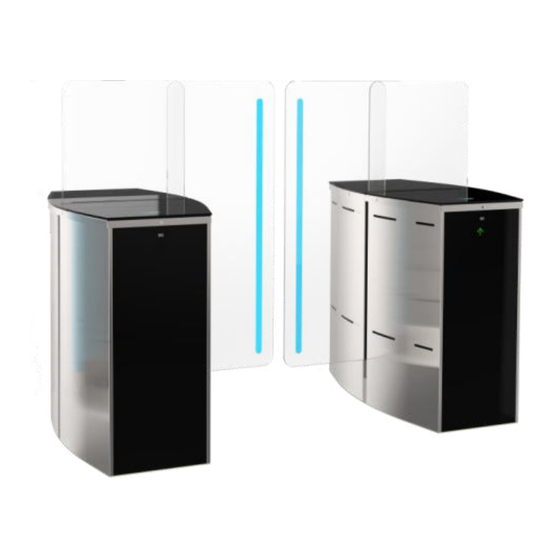
1. DESCRIPTION AND OPERATION 1.1 General Information and Designation 1.1.1 Purpose: JetPan-900- is ideally suited for areas with unmanned security, as higher wings prevent vaulting over the turnstile, wide passage is specially designed to ensure comfortable access. The JetPan-900 is also fitted with optical sensors to prevent tailgating. - Page 6 1.1.3 The turnstile component identification code is specified in Table 2. Table 2 - Dimensions turnstile Dimensions, mm Max. Description of the turnstile component Order code weigh, Height Width Length One side cabinet Т3.КСD.XK “JetPan-900-1.2” Slave АUIA.169-03.1 “JetPan-900-1.1” Master АUIA.169-03.1 Т3.КСD.XK 1520 /1800 615 /620*...
-
Page 7: Specifications
1.1.4 The operation condition parameters according to GOST 15150-69 for climatic modification NF4 are specified in Table 3. Table 3 - The operation condition parameters Operation conditions Parameter value for climatic modification NF4 Ambient air temperature +1°С to +40°С Relative air humidity 80% at +20ºС... - Page 8 – set of side panels; – retractable glass leaf; – fixed glass leaf; – top lid (solid glass top or stainless steel top with plastics inserts); – front panel (or LCD panels or lightboxes - determined by order) – two LED displays. There are installed inside cabinet: –...
-
Page 9: Design And Operation
1.4 Design and operation 1.4.1. Turnstile design The cabinet body is a set of side panels (9) from stainless steel (See Fig.4-5), which are securely fixed to frame and installed on base (8). A decorative lid (6) is mounted on the top of frame (finishing material is determined by order). An additional fixed glass leaf (5) with 10 mm tempered safety glass is mounted in the center of body to prevent unauthorized intrusion along the upper horizontal surface of the body The turnstile’s status is displayed by (2) DotLights... -
Page 10: General Appearance Of The Turnstile Operating Mechanism And Control Desk
1.4.2 General appearance of the turnstile operating mechanism and control desk - place for identification card reader with LED - end position stops of leaf; (RFIDLights - linear guide rails; - LED display (DotLights - IR access sensors ; - linear guideway;... -
Page 11: Principle Of Operation
1.4.3 Principle of operation 1) Turnstile status indication LED lighting of leaves showing access status; - LED lighting display showing - LED Light of card reader area; access status; Fig.6 – Light indication of the turnstile status 2) Access cycle: Standby mode 1. -
Page 12: Description And Operation Of Controllers As Integral Component Of The Turnstile
1.5 Description and operation of controllers as integral component of the turnstile 1.5.1 Main controller АUIA.206.21.20.00 1.5.1.1 Description of operation The controller provides algorithm of operation of the whole turnstile. It is assembled on the 120 х 80 mm size card from foil-clad textile laminate, on which electronic components and terminals for connection to other turnstile units as well as for connection to control peripherals (ACS, control panel etc.) are located. - Page 13 Thus red LED is blinking from the side of locked access, glass leaves are closed (if the turnstile is not open for free or single access from opposite side), controller does not respond to signals of inputs "INP1" ("ACCESS А TO BE OPENED") or/and «INP2»...
- Page 14 Table 6- The purpose of the controller contacts АUIA.206.21.20.00 № Signal description and Description Direction Designation Connecto parameters r/contact 1) logical «0» (0÷2,2) V; INP1 («TO BE ХТ4/1 Command "TO BE OPENED ENTRY 2) logical «1» (3 ÷5) V; OPENED A») FOR SINGLE / FREE 3) active level of signal INP2 («TO BE OPENED...
-
Page 15: Motor Controller Pcb.201.01.00.00
1.5.2 Motor controller PCB.201.01.00.00 1.5.2.1. Description of motor controller PCB.201.01.00.00 Appearance of controller РСВ.201.01.00.00 is shown in Figure 9. 1.6.2.2 Description of operation The controller is designed to control DC motor, intended to move the turnstile blades, and electromagnetic brake installed on motor shaft. -
Page 16: Intended Use
2. INTENDED USE 2.1 Operation restrictions 2.1.1The turnstile must be used in the environment specified in p. 1.1.4 of this document subject to the specifications listed in section 1.2. 2.1.2 It is forbidden to use the turnstile: – at the presence of mechanical rattle in movable parts of the turnstile; –... - Page 17 2.2.5 General layout of the “JetPan-900” turnstile passage ways (Fig.11) Fig. 11 – «JetPan-900» type turnstile layout options...
-
Page 18: Installation Procedure
2.3 Installation procedure. WARNING: When the turnstile damages are detected or in case of shortage of delivery installation work to be stopped and the turnstile supplier to be referred to. The turnstile installation and fixation to be performed only after all electric cables to be connected to the turnstile are pulled The turnstile is fixed by means of Redibolt (with jacket and screw) included in the scope of delivery 1) The turnstile installation procedure is as follows:... - Page 19 IMPORTANT! Cabinets are linked by control line optical sensor system requiring accurate positioning of cabinets. The relative position of cabinets and vertical position of the turnstile to be respected. Cable entry must be carried out in corrugated or metal pipes. The lengths of the free ends of the cables must be at least 1 m to provide input, cut and connect them to the corresponding terminals in the turnstile frame.
- Page 20 Option 1 Option 2 Fig. 15 – Options of cable connection between cabinets Master and Slave of “JetPan-900”...
- Page 21 General assembly and installation of cabinet of “JetPan-900” turnstile To provide access to fixation holes and terminal blocks from both sides of cabinet it is required to: 1. – remove the turnstile lid by unscrewing screws on the ends (See Fig. 16); 2.
- Page 22 7) Installation of proximity card reader upon availability of access control system (ACS) (See Fig. 22). 1 - The turnstile top lid (a) and inner lining of the turnstile to be removed; Screws to be unscrewed and protective screen (acrylate) (b) to be removed. 2 - The card reader (d) to be istalled: Option І- on adjustable...
-
Page 23: Preparation For Use
2.4 Preparation for use 2.4.1 Commission guidelines Prior to the turnstile energization 1) make sure of proper connection and good condition of all connecting cables; 2) clear the turnstile leaf opening area from foreign particles. When mains cable of power supply unit is connected to the network, the turnstile actuating mechanism is energized. -
Page 24: Contingency Actions
Continuation of table 8 Make sure that glass "LOCK" button to be pushed 9. Locked access in Red LED of locked access in leaves are locked and they for locking access in chosen one direction one chosen direction is lit can't be pushed inside the direction (“A”... -
Page 25: Maintenance
3. MAINTENANCE 3.1 General guidelines 3.1.1 Commissioning and subsequent maintenance of the turnstile to be performed only by the staff being in charge of the turnstile. 3.1.2 The turnstile to be serviced only by the staff having the relevant electrical safety qualification level according to the national requirements. -
Page 26: Routine Maintenance
4. ROUTINE MAINTENANCE 4.1 Possible malfunctions Minor malfunctions of the turnstile are listed in Table 10 and to be remedied by the customer. More complicated malfunctions to be remedied by the manufacturer’s representative IMPORTANT: INSPECTION, CLEANING, REPAIR OF THE TURNSTILE COMPONENTS TO BE PERFORMED ONLY AFTER THE TURNSTILE IS DEENERGIZED ! 4.2 Possible malfunctions Possible malfunctions of the turnstile and their remedies are listed in Table 10. -
Page 27: Adjustment Of The Zero Position Of Leaf For Jetpan-900 Gates
4.3 Adjustment of the zero position of leaf for JetPan-900 gates 1. To provide access to the control panel and the turnstile mechanism from both sides of cabinet it is required to: remove the turnstile lid side panels (b1), (b2) (b3) by unscrewing screws on the turnstile frame;... -
Page 28: Transportation And Storage
5. TRANSPORTATION AND STORAGE 5.1 Turnstile storage It is forbidden to subject the turnstile to jerks and impacts during storage. Transportation trolleys to be used for handling of the turnstile. In storage facilities there should not be aggressive gases and vapours causing metal corrosion. Air temperature during storage should not be below +50°... -
Page 29: Annex А.1 - Overall And Installation Dimensions Of The Set Of Turnstile Jetpan-900 (Set Of Master And Slave)
Annex А.1 - Overall and installation dimensions of the set of turnstile JetPan-900 (set of Master and Slave) -
Page 30: 900 (With 900+900 Mm Access Way Width)
Annex А.2 - Overall and installation dimensions of the set of Master, Slave и Master/Slave cabinets of turnstile JetPan-900 (with 900+900 mm access way width) -
Page 31: 900 (With 500+900 Mm Access Way Width)
Annex А.3 - Overall and installation dimensions of the set of Master, Slave и Master/Slave cabinets of turnstile JetPan-900 (with 500+900 mm access way width) -
Page 32: Annex B. Control Panel And Connection Diagram
Annex B. Control panel and connection diagram 1 – control panel body; 2 – "SINGLE ACCESS" mode control button 3 – front plate; 4 – "LOCK" mode control button; 5 – "FREE ACCESS" mode control button 6 – "PANIC" mode control button 7 –... -
Page 33: Annex C.1. Wiring Diagram Of Jetpan-900 1.1 Master (Auia.169-03) Rev 2.0
Annex C.1. Wiring diagram of JetPan-900 1.1 Master (AUIA.169-03) rev 2.0 ВЕД УЩАЯ СТОЙКА КОНТ Р ОЛЛЕР Контроллер Контроллер PCB.205.01.05.00 АЮИА. 206.21.20.00 Коричневый (BROUN) + PCB 201.01. 00.00 PCB 201.01. 00.00 XP 1 Синий (BLUE) - X T1 +12V Черный (BLACK) NO +12V IR IN 1 +12V... -
Page 34: Annex C.2. Wiring Diagram Of Jetpan -900 1.2 Slave (Auia.169-03) Rev 2.0
Annex C.2. Wiring diagram of JetPan -900 1.2 Slave (AUIA.169-03) rev 2.0 П р о в о д а к в е д у щ е й с т о й к е ВЕДОМАЯ СТОЙКА PCB.205.01.05.00 XS25 Контроллер Контроллер +12V PCB 201.01. -
Page 35: Annex C.3. Wiring Diagram Of Jetpan-900-2 Master/Slave (Auia.169-03) Rev 2.0
Annex C.3. Wiring diagram of JetPan-900-2 Master/Slave (AUIA.169-03) Rev 2.0... -
Page 36: Annex D.1. Diagram Of The Turnstile Connection To Access Control System (Acs)
Annex D.1. Diagram of the turnstile connection to access control system (ACS) Relay 1 Relay 2 Door contact 1 Door contact 2 inp1 - "TO BE OPENED A" in pulse mode. When command is issued entry is activated for 5 sec. inp2- "TO BE OPENED B"... -
Page 37: Annex D.2. Diagram Of The Turnstile Connection To Access Control System (Acs)
Annex D.2. Diagram of the turnstile connection to access control system (ACS) inp1- " TO BE OPENED A" in pulse mode. When command is issued the input is activated for 5 sec. . inp - 2 " TO BE OPENED B" in pulse mode. When command is issued the input is activated for 5 seconds. -
Page 38: Annex D.3. Diagram Of The Turnstile Connection To Fire Alarm (Fa)
Annex D.3. Diagram of the turnstile connection to fire alarm (FA) inp1- " TO BE OPENED A" in pulse mode. When command is issued the input is activated for 5 sec. inp - 2 " TO BE OPENED B" in pulse mode. When command is issued the input is activated for 5 seconds. -
Page 39: Annex D.4. Diagram Of The Turnstile Connection To Control Panel
Annex D.4. Diagram of the turnstile connection to control panel 5 4 3 2 1... - Page 40 Manufacturer: LLC TiSO-PRODUCTION 14, Promyslova Street, Kyiv, 02088, Ukraine Phone: +38 (044) 291-21-11 Tel./fax: +38 (044) 291-21-02 E-mail: sales@tiso.global www.tiso.global SERVICE CENTER e-mail: service1@tiso.global Our equipment complies with requirements of the European Standards: EN ISO 12100:2010, EN ISO 14118:2018, EN 60204-1:2018, EN ISO 13857:2019,...
Need help?
Do you have a question about the Speed Gate JETPAN-900 Series and is the answer not in the manual?
Questions and answers